Thermal Embossing Unit for Optical Fiber Cables

A fiber optic cable and thermal embossing technology, which is applied in the field of thermal embossing devices, can solve the problems of crushed product quality, accidents, and thinning of the sheath at the embossed place, and achieve complete printing content, product quality assurance, and versatility Good results

Active Publication Date: 2019-06-28
JIANGSU HENGTONG PHOTOELECTRIC +1
View PDF5 Cites 1 Cited by
  • Summary
  • Abstract
  • Description
  • Claims
  • Application Information

AI Technical Summary

Problems solved by technology

The disadvantage of using spray printing is that the printed identification content is easily wiped off after the wires and cables are rubbed by transportation bumps, laying and dragging, and the printing content has poor adhesion
The disadvantages of using the single-line embossing form of the printing wheel are: (1) Restricted by factors such as the roundness of the wire and cable and the positioning stability during the production of the wire and cable, it is easy to appear unclear printing; (2) Due to the unilateral impact of the wire and cable sheath The force will cause the thickness of the sheath at the embossed part to become thinner, or even crushed, resulting in product quality accidents; (3) After the actual laying of the wire and cable, if the printed content is laid below, it is easy to cause the phenomenon that the wire and cable model specification is not convenient to check
The above two marking forms have adverse effects on the manufacture, laying-out construction and later maintenance of wires and cables.

Method used


Image

  • Thermal Embossing Unit for Optical Fiber Cables
  • Thermal Embossing Unit for Optical Fiber Cables
  • Thermal Embossing Unit for Optical Fiber Cables

Examples


Embodiment 1

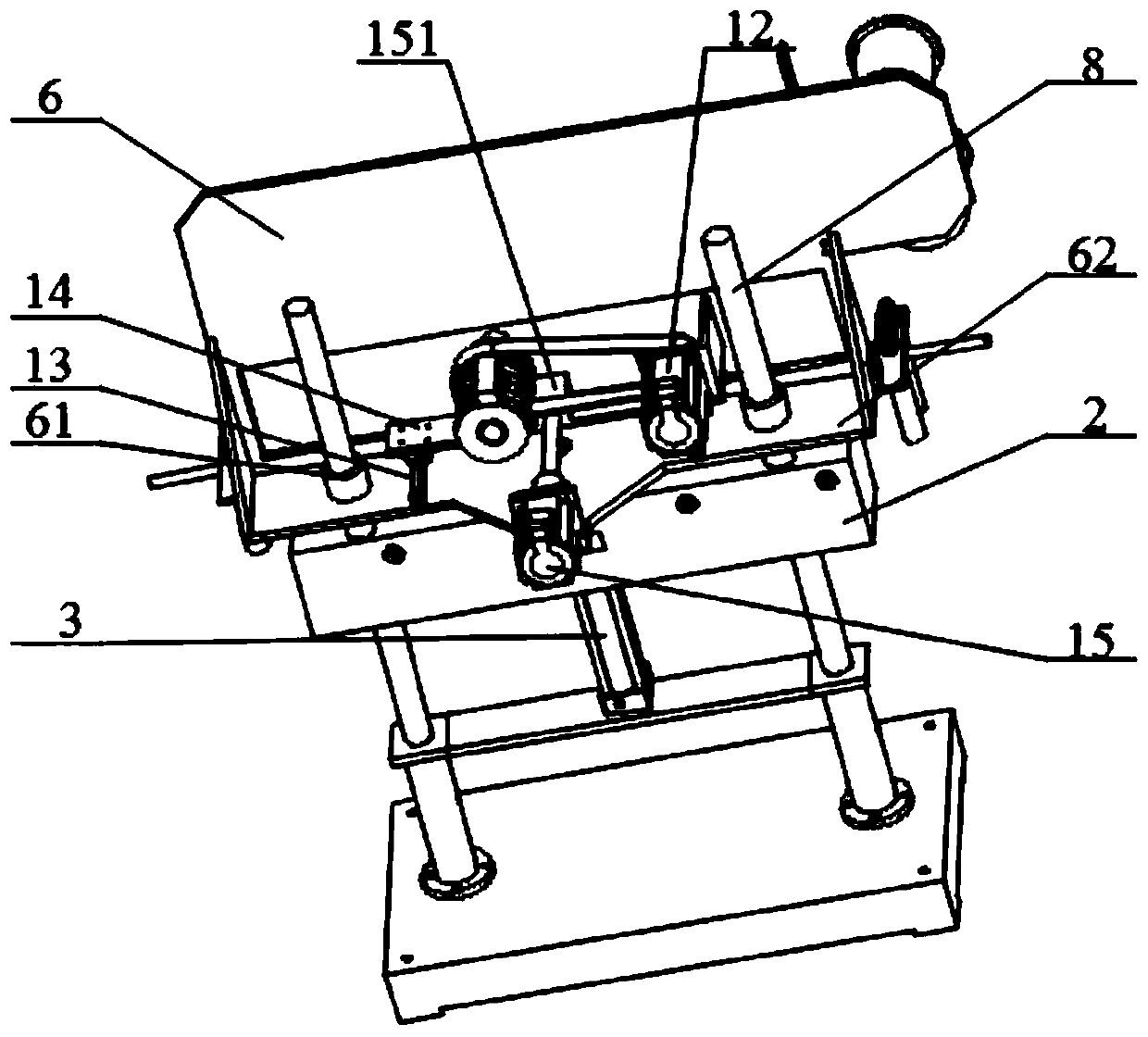
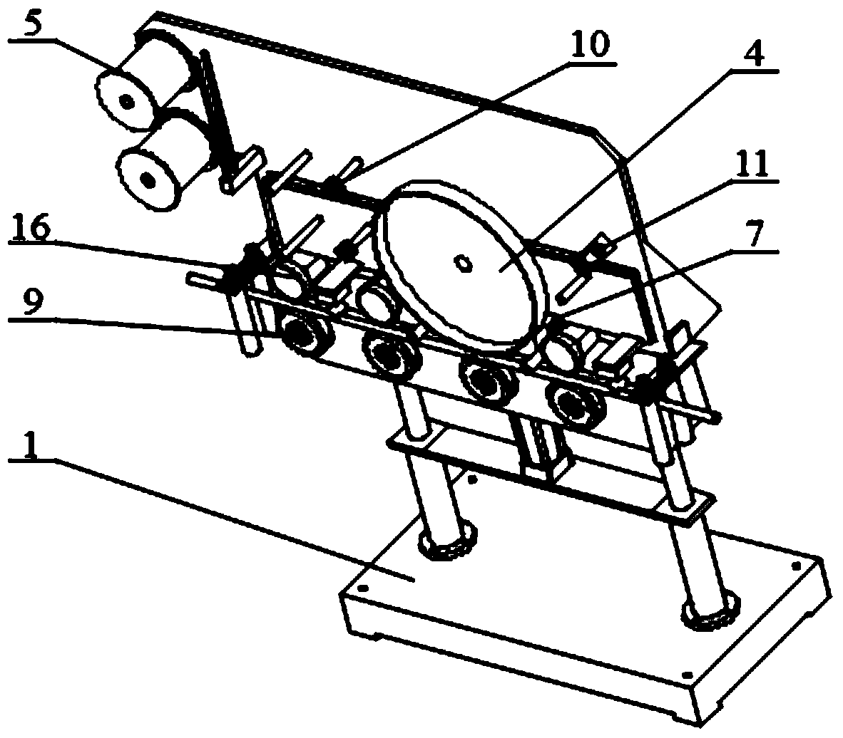
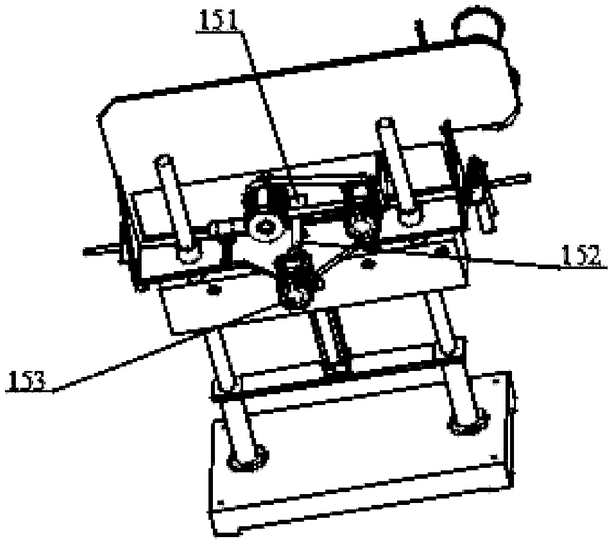
[0024] Embodiment 1: A thermal embossing device for an optical fiber cable, comprising: a base 1, a fixed seat 2, a tension adjustment cylinder 3, a thermal embossing wheel 4, a ribbon mounting disc 5 wrapped with a ribbon, a lifting plate 6 and a flat plate Moving plate 7, two left and right guide shafts 8 fixed on the upper surface of the base 1, the fixed seat 2 is fixed in the middle of the two guide shafts 8, and the front side of the fixed seat 2 is provided with several A supporting fixed wheel 9, the lifting plate 6 has two guide sleeves 61 arranged left and right, the guide shaft 8 positioned above the fixed seat 2 is embedded in the guide sleeve 61 of the lifting plate 6;

[0025] The ribbon mounting disc 5 is installed on the front surface of the lifting plate 6, and a guide wheel 10 fixed to the lifting plate 6 or the flat plate 7 is arranged between the ribbon mounting disc 5 and the hot embossing wheel 4. An air duct 11 for absorbing the ribbon is fixed on the si...

Embodiment 2

[0030] Embodiment 2: A thermal embossing device for an optical fiber cable, including: a base 1, a fixed seat 2, a tension adjustment cylinder 3, a thermal embossing wheel 4, a ribbon mounting disc 5 wrapped with a ribbon, a lifting plate 6 and a flat Moving plate 7, two left and right guide shafts 8 fixed on the upper surface of the base 1, the fixed seat 2 is fixed in the middle of the two guide shafts 8, and the front side of the fixed seat 2 is provided with several A supporting fixed wheel 9, the lifting plate 6 has two guide sleeves 61 arranged left and right, the guide shaft 8 positioned above the fixed seat 2 is embedded in the guide sleeve 61 of the lifting plate 6;

[0031] The ribbon mounting disc 5 is installed on the front surface of the lifting plate 6, and a guide wheel 10 fixed to the lifting plate 6 or the flat plate 7 is arranged between the ribbon mounting disc 5 and the hot embossing wheel 4. An air duct 11 for absorbing the ribbon is fixed on the side of t...


PUM


Abstract

The invention discloses a hot stamping device for optical fiber and cable. The hot stamping device for optical fiber and cable comprises a pedestal, a fixed base, a tension adjusting cylinder, a hot stamping wheel, colored tape mounting disks with wounded colored tapes, a lifting board and a translation plate, wherein the hot stamping wheel and a plurality of press wheels are arranged on the front surface of the translation plate; a rotation servo motor is arranged on the surface, being opposite to the hot stamping wheel, on the translation plate, and is used for driving the hot stamping wheel to rotate; the translation plate is arranged at the front of the lifting board; two linear tracks are arranged on the upper surface of a base plate of the lifting board in parallel, and move in the front and back direction; two sliding blocks are arranged at the lower surface of the base plate of the translation plate; the two linear tracks are respectively embedded into respective grooves of the two sliding blocks; the tension adjusting cylinder is vertically arranged on the pedestal, and a cylinder barrel of the tension adjusting cylinder is fixed on the pedestal; and the tail end of a piston rod of the tension adjusting cylinder is connected with the base plate of the lifting board. The hot stamping device for optical fiber and cable can stamp distinct and perdurable printing content on the surface of an optical fiber and cable sheath, and the printing content is complete, durable and distinct; and the elastic pressure does not damage the surface of the optical fiber and cable sheath so that the product quality is guaranteed.

Description

technical field [0001] The invention relates to the field of thermal embossing devices, in particular to a thermal embossing device for optical fiber cables. Background technique [0002] At present, the method for marking the surface of the wire and cable sheath in the domestic market is generally through two methods of inkjet printer printing or single-line embossing of the printing wheel. The disadvantage of using spray printing is that the printed marking content is easily wiped off after the wires and cables are rubbed by transportation bumps, laying dragging and other links, and the printing content has poor adhesion. The disadvantages of using the single-line embossing form of the printing wheel are: (1) Restricted by factors such as the roundness of the wire and cable and the positioning stability during the production of the wire and cable, it is easy to appear unclear printing; (2) Due to the unilateral impact of the wire and cable sheath The force will cause the ...

Claims


Application Information

Patent Timeline
Patent Type & Authority Patents(China)
IPC IPC(8): G02B6/44
CPCG02B6/4479G02B6/4482
Inventor 轩传吴嵇德海江荣李兴进李一村孙瑜滢彭朋苇何兰珍潘荣华朱芳银李云
Owner JIANGSU HENGTONG PHOTOELECTRIC
Why Eureka
Try Eureka