High-energy ion field generating device and ion field generating method

A high-energy ion and field generation technology, applied in the field of ions, can solve the problems of decreased stability of high-energy ion field devices, increased equipment failure rate, large size of the device, etc., so as to improve the ion generation efficiency, prolong the service life, and reduce the volume.

Active Publication Date: 2016-09-21
XINJIANG 830009
View PDF3 Cites 0 Cited by
  • Summary
  • Abstract
  • Description
  • Claims
  • Application Information

AI Technical Summary

Problems solved by technology

[0005] (1) When multiple plasma annular chambers are arranged in the same high-energy ion field generating device, multiple insulator support devices need to be used, which leads to a large volume of the entire high-energy ion field generating device and takes up more space;
[0006] (2) After the high-energy ion field generating device has been used for a period of time, the outer wall of the insulator support device is often covered with a layer of moist dust, which leads to the failure of the insulator support device and makes the positive and negative electrodes electrified, resulting in the generation of high-energy ion field The stability of the device decreases. In severe cases, the high-voltage power supply will not change with the change of the load condition, resulting in an increase in the failure rate of the equipment

Method used


Image

  • High-energy ion field generating device and ion field generating method
  • High-energy ion field generating device and ion field generating method
  • High-energy ion field generating device and ion field generating method

Examples


Embodiment Construction

[0052] In order to make the technical problems, technical solutions and beneficial effects solved by the present invention clearer, the present invention will be further described in detail below with reference to the accompanying drawings and embodiments. It should be understood that the specific embodiments described herein are only used to explain the present invention, but not to limit the present invention.

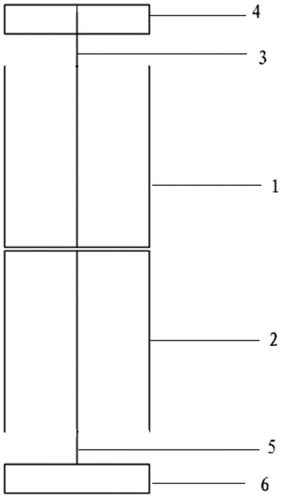
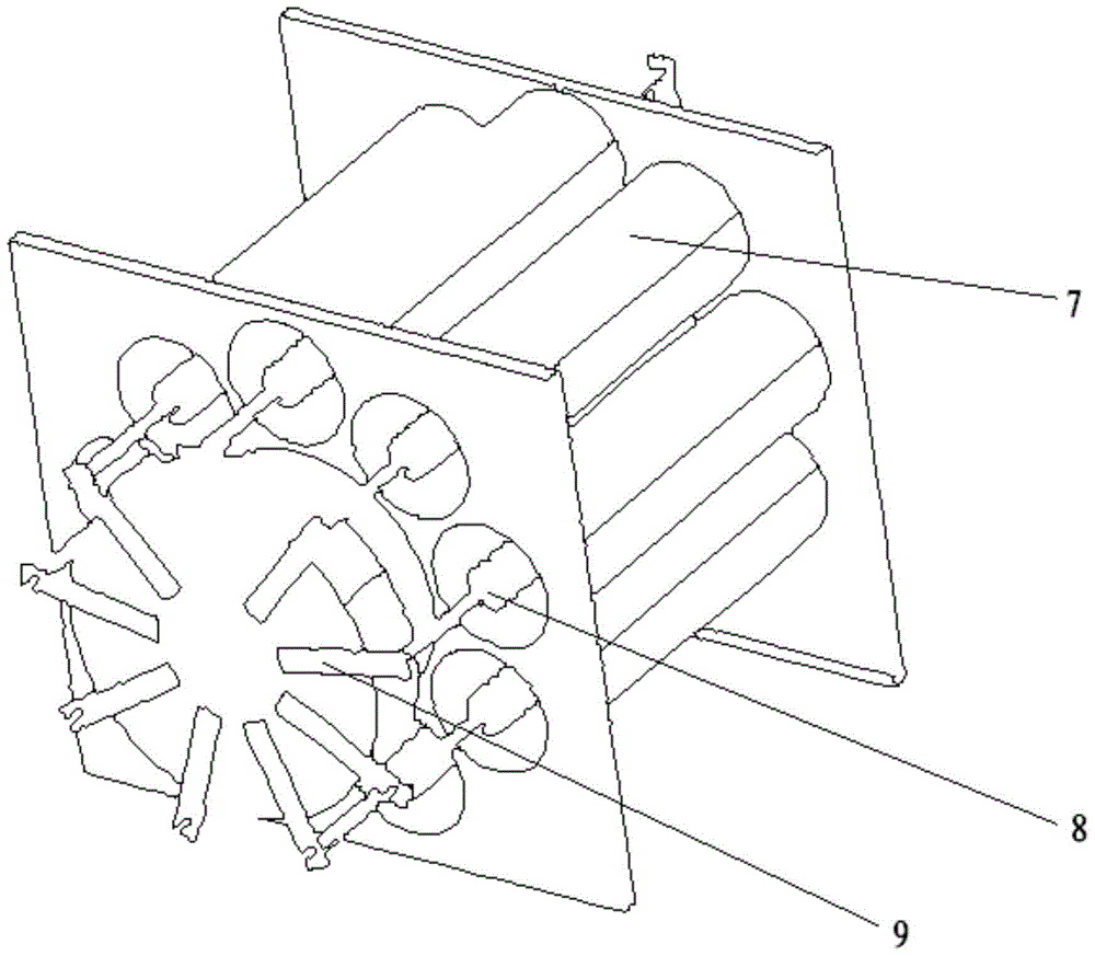
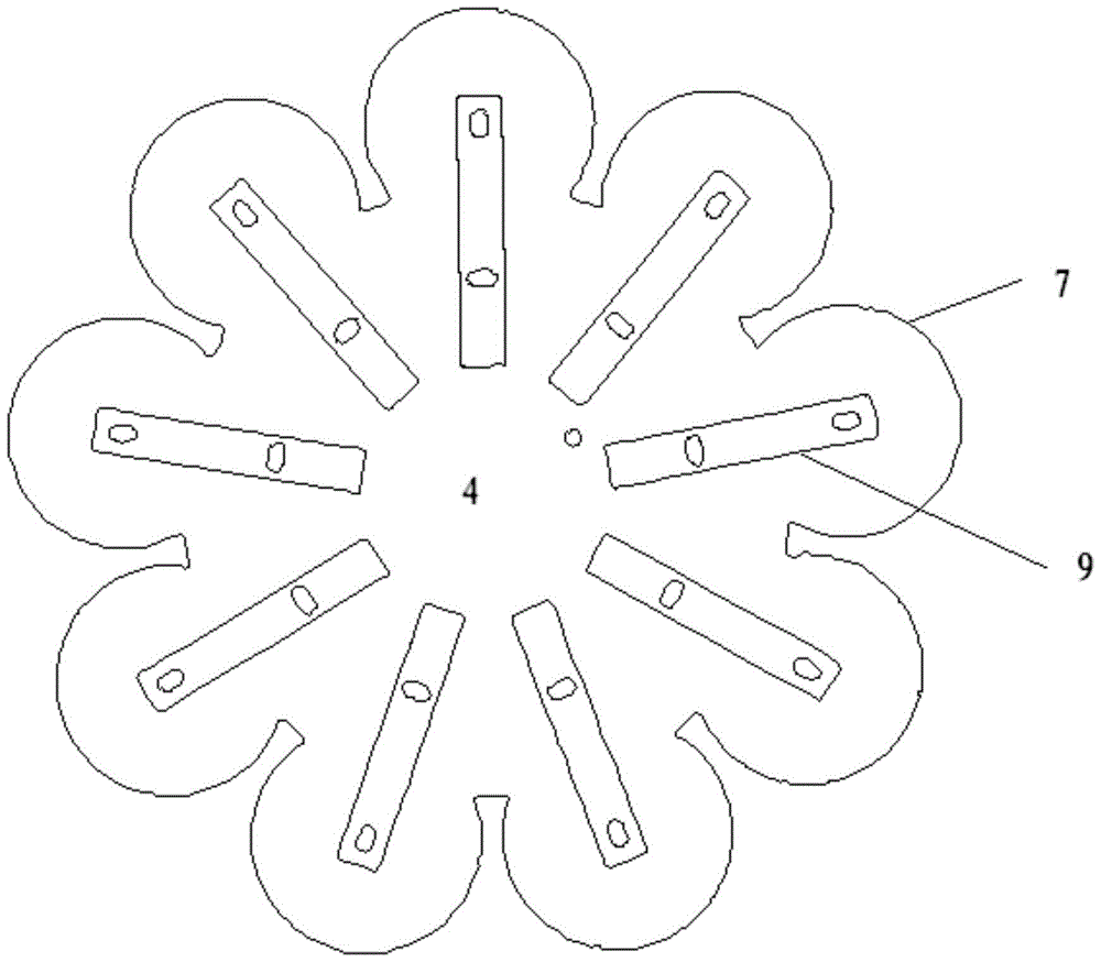
[0053] The present invention provides a high-energy ion field generating device, comprising an upper insulator protective cover 1 and a lower insulator protective cover 2; the upper insulator protective cover 1 and the lower insulator protective cover 2 are both cylindrical structures with one end open and one end sealed, and the upper insulator protective cover 1 The opening is arranged upward, the lower insulator protective cover 2 is arranged below the upper insulator protective cover 1, and the opening is arranged downward; both the upper insulator protective cove...


PUM


Abstract

The invention provides a high-energy ionic field generation device and an ionic field generation method. The high-energy ionic field generation device comprises an upper insulator protection jacket and a lower insulator protection jacket, wherein an upper insulator is arranged at the axis position of the upper insulator protection jacket, a lower insulator is arranged at the axis position of the lower insulator protection jacket, n negative electrodes are arranged at the peripheries of the insulator protection jackets in an circular or arc way, a positive electrode is arranged at the axis position of each negative electrode, the top end of the positive electrode is fixed on an upper installation seat by a first fixed arm, and the bottom end of the positive electrode is fixed on an lower installation seat by a second fixed arm. The high-energy ionic field generation device has the advantages that the occupancy space of the device can be effectively saved, the volume of the device is shortened, the outer walls of the insulators can be prevented from being covered by a layer of humid dust due to long-term use, so that the insulator failure is prevented, the service lifetime of the device is prolonged, and the long-term safe and stable application of the device is further ensured; and the positive electrodes can adopt metal hard rods and also can adopt metal flexible wires, and thus, the application range of the device is expanded.

Description

technical field [0001] The invention belongs to the technical field of plasma, and in particular relates to a high-energy ion field generating device and an ion field generating method. Background technique [0002] The structure of the ion field generator is mainly: including positive and negative electrodes insulated from each other; the positive electrode is in the shape of a hollow cylinder; the negative electrode is in the shape of a rod, and a plasma annular chamber is formed between the positive electrode and the negative electrode. When a potential difference is generated between the positive electrode and the negative electrode, plasma can be generated, and the generated plasma can break the molecular chains of organic substances in the annular chamber, so as to purify the air and improve the living environment of people. [0003] In the ion field generating device existing in the prior art, the negative electrode needs to be supported and fixed by an insulator supp...

Claims


Application Information

Patent Timeline
Patent Type & Authority Patents(China)
IPC IPC(8): H01T23/00
CPCH01T23/00
Inventor 韩汶冀赵永德韩易谋
Owner XINJIANG 830009
Why Eureka
Try Eureka