Asymmetric permanent magnet motor for new energy automobile

A new energy vehicle, permanent magnet motor technology, applied in the direction of magnetic circuits, electrical components, electromechanical devices, etc., can solve the problems of vibration and noise amplification, reduce output, increase copper consumption, etc., to reduce mechanical vibration, reduce core loss, The effect of high power density

Inactive Publication Date: 2016-03-30
SHANGHAI TOP MOTOR +1
View PDF10 Cites 15 Cited by
  • Summary
  • Abstract
  • Description
  • Claims
  • Application Information

AI Technical Summary

Problems solved by technology

The motor industry and research institutes all over the world are doing research to reduce the torque fluctuation of the motor, such as the use of fractional slot method, auxiliary slot method, auxiliary tooth method, inclined slot method, oblique pole method, closed slot method and magnetized slot wedge method, etc. Each has advantages and disadvantages, but it is always difficult to effectively eliminate the cogging effect
Inclined slots or inclined poles are the most commonly used methods to reduce torque fluctuations, but the inclined slot method has an impact on the flat-top width of the air-gap magnetic induction intensity of square wave motors. At the same time, stator inclined slots will affect the slot area occupied by conductors and increase copper consumption. , both of which reduce the output and complicate the process and structure of the motor
The high-precision speed control system has strict requirements on the cogging torque fluctuation, because in the speed control system, when the frequency of the motor torque is consistent with the mechanical resonance frequency of the stator or rotor, the vibration and noise generated by the cogging torque are significantly amplified, and at the same time Also affects low-speed performance and positioning accuracy

Method used


Image

  • Asymmetric permanent magnet motor for new energy automobile
  • Asymmetric permanent magnet motor for new energy automobile
  • Asymmetric permanent magnet motor for new energy automobile

Examples


Embodiment Construction

[0023] The embodiments of the present invention are described in further detail below in conjunction with the accompanying drawings, but the present embodiments are not intended to limit the present invention. All similar structures and similar changes of the present invention should be included in the scope of protection of the present invention. The commas in all indicate the relationship between and.

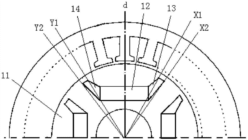
[0024] Such as figure 1 As shown, an asymmetric permanent magnet motor for new energy vehicles provided by the first embodiment of the present invention includes a rotor and a stator, and the rotor 11 is provided with a plurality of permanent magnet units, and the permanent magnet units include permanent magnet units. The magnetic groove, and the magnetic steel 12 embedded in the permanent magnetic groove, are characterized in that: the magnetic pole axis d of the rotor 11 divides the permanent magnet unit into two halves, and the left half and the right half of the permanent...


PUM


Abstract

The invention discloses an asymmetric permanent magnet motor for a new energy automobile, relates to the technical field of motors, and aims to lower torque fluctuation. The motor comprises rotors and a stator, wherein a plurality of permanent magnet units are arranged on the rotors; and the permanent magnet units comprise permanent magnet grooves and magnetic steel embedded into the permanent magnet grooves. The asymmetric permanent magnet motor is characterized in that magnetic pole axes of the rotors partition the permanent magnet units into left halves and right halves; and the left halves and the right halves of the permanent magnet units have different structures. Through adoption of the motor provided by the invention, the comprehensive performance of the motor can be enhanced.

Description

technical field [0001] The invention relates to motor technology, in particular to an asymmetrical permanent magnet motor technology for new energy vehicles. Background technique [0002] In recent years, the replacement cycle of permanent magnet electromechanical products is very fast, and the requirements for high efficiency, low noise, low price, wide speed regulation and intelligence are put forward for the supporting motors. The permanent magnet drive motor has developed from "DC brushless to permanent magnet synchronous"; from "surface-mounted permanent magnet rotor to built-in permanent magnet rotor"; from "single motor function to starting and generating integrated (ISG) function" trend. Therefore, the concept of motor design must be updated: 1) The best motor design principles should not be satisfied with achieving the best performance, but should be the best performance-price ratio and the best performance-to-volume ratio; 2) The motor design should also be consid...

Claims


Application Information

Patent Timeline
Patent Type & Authority Applications(China)
IPC IPC(8): H02K1/27
CPCH02K1/2706H02K2201/06
Inventor 林德芳
Owner SHANGHAI TOP MOTOR
Why Eureka
Try Eureka