Desk-type cutting tool

A cutting tool and desktop technology, applied in the field of desktop cutting tools, can solve the problems of low transmission efficiency, environmental pollution, complex assembly structure, etc.

Inactive Publication Date: 2016-03-30
ZHEJIANG LVDONG MOTOR TECH CO LTD
View PDF5 Cites 4 Cited by
  • Summary
  • Abstract
  • Description
  • Claims
  • Application Information

AI Technical Summary

Problems solved by technology

[0002] Existing desktop cutting tools are usually driven by motors, and the motors usually use series-excited motors. This type of series-excited motor has a carbon brush structure, and the series-excited motor realizes current commutation through carbon brushes at the same time. One of the bottlenecks of the service life of the tool, and the wear and tear of the carbon brush produces carbon powder, which has caused some pollution to th

Method used


Image

  • Desk-type cutting tool
  • Desk-type cutting tool
  • Desk-type cutting tool

Examples


Embodiment Construction

[0019] The core of the present invention is to provide a desktop cutting tool, which has a simple and compact structure, long service life and high transmission efficiency.

[0020] In order to enable those skilled in the art to better understand the solution of the present invention, the present invention will be further described in detail below in conjunction with the accompanying drawings and specific embodiments.

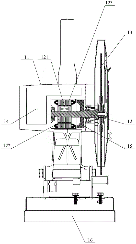
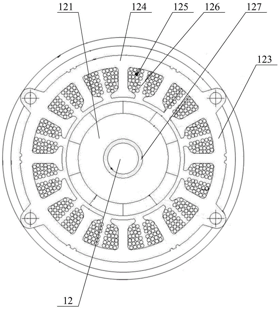
[0021] Please refer to figure 1 and figure 2 , figure 1 A schematic structural view of a desktop cutting tool provided for a specific embodiment of the present invention; figure 2 for figure 1 A schematic diagram of the axial structure of the brushless motor part.

[0022] In a specific embodiment, the desktop cutting tool provided by the present invention includes a casing 11, and a brushless motor and a controller 14 are arranged inside the casing 11. The brushless motor includes a motor shaft 12, and the outer surface of the motor shaft 12 is The end ...


PUM


Abstract

The invention discloses a desk-type cutting tool, and the tool comprises a case. The interior of the case is provided with a brushless motor and a controller, wherein the brushless motor comprises a motor rotating shaft. An external end part of the motor rotating shaft is provided with an output disc in a linkable sleeving manner, and the axis of the motor rotating shaft is perpendicular to the operation surface of the output disc, and passes through the center of the output disc. The periphery of the internal end of the motor rotating shaft is coaxially provided with a rotor core in a sleeving manner, and the peripheral surface of the rotor core is provided with a permanent magnet. The interior of the case is also provided with a stator cooperating with the permanent magnet. The tool is simple and compact in structure, is longer in service life, and is higher in transmission efficiency.

Description

technical field [0001] The invention relates to the technical field of machining equipment, in particular to a desktop cutting tool. Background technique [0002] Existing desktop cutting tools are usually driven by motors, and the motors usually use series-excited motors. This type of series-excited motor has a carbon brush structure, and the series-excited motor realizes current commutation through carbon brushes at the same time. One of the bottlenecks of the service life of the tool, and the wear and tear of the carbon brush produces carbon powder, which has caused some pollution to the environment; The transmission direction change and deceleration purpose between the output shaft and the output shaft. However, due to the presence of many transmission parts such as gears in this assembly structure, the transmission efficiency is low, and the overall required assembly space is relatively large, and the assembly structure is relatively complicated; at the same time, the ...

Claims


Application Information

Patent Timeline
IPC IPC(8): H02K7/14H02K1/27H02K1/20B23D47/00
Inventor 应时立周加泽
Owner ZHEJIANG LVDONG MOTOR TECH CO LTD
Why Eureka
Try Eureka