Supercharge Your Innovation With Domain-Expert AI Agents!

High porosity abradable coating

A porosity, coating technology for gas turbine engine applications

Active Publication Date: 2016-03-30
SOLAR TURBINES
View PDF4 Cites 0 Cited by
  • Summary
  • Abstract
  • Description
  • Claims
  • Application Information

AI Technical Summary

Problems solved by technology

Intermediate layer applied to bond coat

Method used


Image

  • High porosity abradable coating
  • High porosity abradable coating
  • High porosity abradable coating

Examples


Embodiment Construction

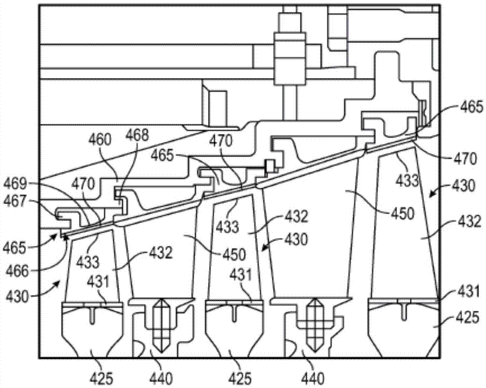
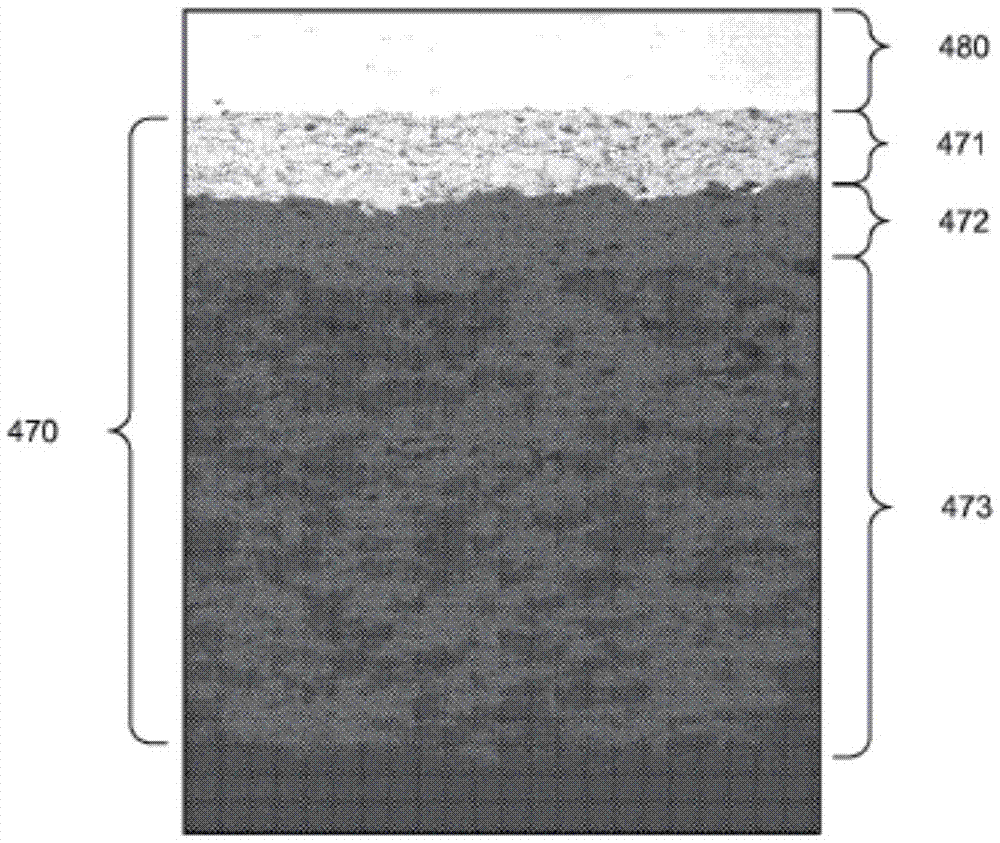
[0008] The systems and methods disclosed herein include abradable coatings for gas turbine engine components. In an embodiment, the abradable coating includes a bond coating, an intermediate layer, and a porous layer. The bond coating includes a metal material, the intermediate layer includes a ceramic material, and the porous layer includes a ceramic material having a porosity (for example, 35% or more of its volume). The bond coat and intermediate layer can provide support and structure for the porous layer. The intermediate layer can also improve the durability of the abradable coating. The porous layer can reduce the wear of the turbine blade and the bare metal tip or the turbine blade without wearing the ceramic tip.

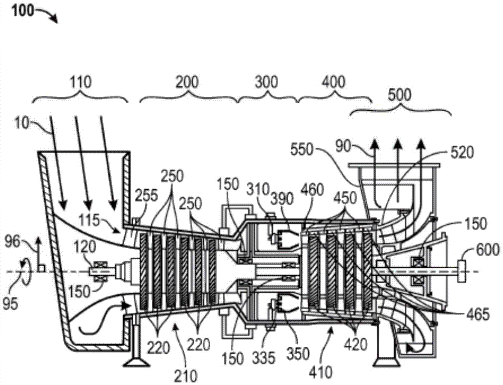
[0009] figure 1 It is a schematic diagram of an exemplary gas turbine engine 100. For clarity and ease of description, some surfaces have been omitted or enlarged (in this figure and other figures). In addition, the present invention may refer to a forward...


PUM

PropertyMeasurementUnit
thicknessaaaaaaaaaa
thicknessaaaaaaaaaa
thicknessaaaaaaaaaa

Abstract

An abradable coating for a gas turbine engine includes a bond coat, an intermediate layer, and a porous layer. The bond coat includes a metal coating and a thickness from 0.152 millimeters to 0.229 millimeters. The intermediate layer includes a ceramic material and a thickness from 0.051millimeters to 0.381 millimeters. The porous layer includes a porous ceramic material. The porous layer also includes a porosity greater than thirty-five percent of a volume of the porous layer. The porous layer further includes a thickness from 0.127 millimeters to 1.524 millimeters.

Description

Technical field [0001] The present invention relates generally to gas turbine engines, and more particularly to a high-porosity abradable coating for gas turbine engine components, such as pointed shoes adjacent to exposed rotor blades. Background technique [0002] Gas turbine engines include compressors, combustors, and turbine segments. Components of compressors, combustors, and turbine segments are often coated with abradable coatings and / or thermal insulation coatings. C. Strock’s U.S. Patent Application Publication No. 2012 / 0062888 discloses an abradable coating for interacting with the tip of an airfoil (such as a vane or blade of a compressor of a gas turbine engine), which includes a metal bond Combined thermal coating, ceramic layer, and abradable layer. The ceramic layer on the metal bond coating provides insulation and acts as a fuse, which is suitable for peeling off during high friction interactions. The abradable coating on the ceramic layer contacts the tip of ...

Claims


Application Information

Patent Timeline
Patent Type & Authority Applications(China)
IPC IPC(8): C23C28/00F02C7/28F01D11/08
CPCF01D11/122C23C28/3215C23C28/3455F05D2300/514Y10T428/24967
Inventor B·A·柯顿M·A·科
Owner SOLAR TURBINES
Features
  • R&D
  • Intellectual Property
  • Life Sciences
  • Materials
  • Tech Scout
  • Unparalleled Data Quality
  • Higher Quality Content
  • 60% Fewer Hallucinations
Learn More