Engraving and milling machine with tool magazine device

A library device, engraving and milling machine technology, applied in positioning devices, metal processing machinery parts, clamping, etc., can solve the problems of inconvenient use and replacement, complex overall structure, increased manufacturing costs, etc., to achieve fast tool change time, Guarantee the effect of tool change quality and convenient operation

Active Publication Date: 2016-04-06
湖北铁正机械有限公司
View PDF7 Cites 8 Cited by
  • Summary
  • Abstract
  • Description
  • Claims
  • Application Information

AI Technical Summary

Problems solved by technology

[0002] The engraving and milling machine is a high-precision and efficient automatic cutting machine tool. The existing engraving and milling machine generally includes a base, an X-axis motion mechanism, a Y-axis motion mechanism, a Z-axis motion mechanism, a column, a beam, a worktable, and an electric spindle. And electrical control devices, the existing engraving and milling machine is mainly composed of the main shaft and the tool, because the functions of the engraving and milling machine are gradually increasing, each small function has a matching tool and spare parts, so every engraving and milling machine There are more and more cutting tools and spare parts. However, the defects of engraving and milling machines on the market are: there is no specially reserved space and device to store cutting tools and accessories, which is very inconvenient to use and replace. Traditional knives Because the library and toolbox are external, the tool change time is correspondingly prolonged, and the overall structure is complicated and the manufacturing cost is also increased.

Method used


Image

  • Engraving and milling machine with tool magazine device
  • Engraving and milling machine with tool magazine device
  • Engraving and milling machine with tool magazine device

Examples


Embodiment 1

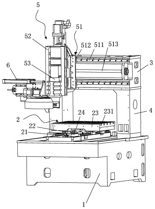
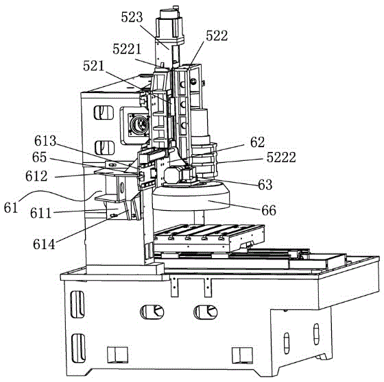
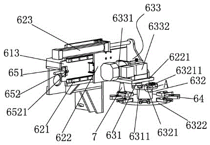
[0033] Example 1: Reference figure 1 , a new type of engraving and milling machine, a kind of engraving and milling machine with a tool magazine device, including a base 1, a mobile worktable 2 arranged on the base 1, a beam 3 arranged above the mobile workbench 2, a 2 The columns 4 on both sides for supporting the beam 3 and the spindle device 5 arranged on the beam 3 are characterized in that they also include a rotary tool magazine device 6, and the rotary tool magazine device 6 includes a fixed bracket 61 fixedly arranged on the side of the column , the moving device 62 that is fixed on the fixed bracket 61, the rotary tool magazine seat 63 that is arranged on the mobile device 62 and some cutter head fixtures 64 that are arranged on the rotary tool magazine seat 63, the cutter head holder 64 is clamped with different types of Cutter head7.

[0034] The fixed bracket 61 includes a fixed side plate 611 for fixing, a fixed upper plate 612 arranged on the fixed side plate 61...


PUM


Abstract

The invention relates to the technical field of machine tools, in particular to an engraving and milling machine with a tool magazine device. The engraving and milling machine with the tool magazine device comprises a base, a movable worktable arranged on the base, a cross beam arranged above the movable worktable, stand columns which are arranged on two sides of the movable worktable and used for supporting the cross beam and a main shaft device arranged on the cross beam, and is characterized by further comprising the rotary tool magazine device. The rotary tool magazine device comprises a fixed supporting frame fixedly arranged on the lateral surface of one stand column, a movable device fixed to the fixed supporting frame, a rotary tool magazine seat arranged on the movable device and a plurality of tool bit clamps arranged on the rotary tool magazine seat and used for clamping tool bits of different specifications. The engraving and milling machine with the tool magazine device has the advantages of being simple in structure, convenient to operate, short in tool changing time and safer, effectively guaranteeing tool changing quality, better guaranteeing stability of the tool bits and the machining accuracy and the like.

Description

technical field [0001] The invention relates to the technical field of processing machine tools, in particular to an engraving and milling machine with a tool magazine device. technical background [0002] The engraving and milling machine is a high-precision and efficient automatic cutting machine tool. The existing engraving and milling machine generally includes a base, an X-axis motion mechanism, a Y-axis motion mechanism, a Z-axis motion mechanism, a column, a beam, a worktable, and an electric spindle. And electrical control device, the existing engraving and milling machine is mainly composed of the main shaft and the tool, because the functions of the engraving and milling machine are gradually increasing, every small function has a matching tool and spare parts, so every engraving and milling machine There are more and more cutting tools and spare parts. However, the defects of engraving and milling machines on the market are: there is no specially reserved space an...

Claims


Application Information

Patent Timeline
IPC IPC(8): B23Q3/157
CPCB23Q3/157
Inventor 戴海永
Owner 湖北铁正机械有限公司
Why Eureka
Try Eureka