Clamp controlling non-rotational symmetry errors for optical elements during polishing

A non-rotationally symmetric, optical element technology, used in manufacturing tools, optical surface grinders, grinding/polishing equipment, etc., can solve the problems of low processing convergence efficiency and difficult polishing, and achieve effective control, high resolution, The effect of ensuring positional stability

Inactive Publication Date: 2016-04-06
CHANGCHUN INST OF OPTICS FINE MECHANICS & PHYSICS CHINESE ACAD OF SCI
View PDF5 Cites 1 Cited by
  • Summary
  • Abstract
  • Description
  • Claims
  • Application Information

AI Technical Summary

Problems solved by technology

[0003] The purpose of the present invention is to propose a jig for polishing optical elements that controls non-rotational symmetry errors, so as to solve the problems of high polishing difficulty and low processing convergence efficiency in the prior art

Method used


Image

  • Clamp controlling non-rotational symmetry errors for optical elements during polishing
  • Clamp controlling non-rotational symmetry errors for optical elements during polishing

Examples


Embodiment Construction

[0013] Embodiments of the present invention will be further described below in conjunction with the accompanying drawings.

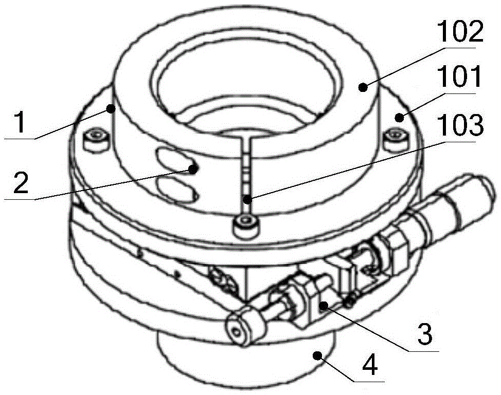
[0014] See attached figure 2 , a jig for controlling non-rotational symmetry error optical element polishing of the present invention includes a clamping sleeve 1, a locking screw A2, a one-dimensional translation stage 3 and a fixed base 4;

[0015] The clamping bushing 1 is fixed on the upper installation surface of the one-dimensional translation platform 3, and the lower installation surface of the one-dimensional translation platform 3 is fixedly connected with the fixed base 4;

[0016] When the adjustment knob of the one-dimensional translation table 3 is at the zero scale, the clamping sleeve 1 is coaxial with the fixed base 4, and the clamping sleeve 1 is a flexible structure, which is locked by the locking screw A2 .

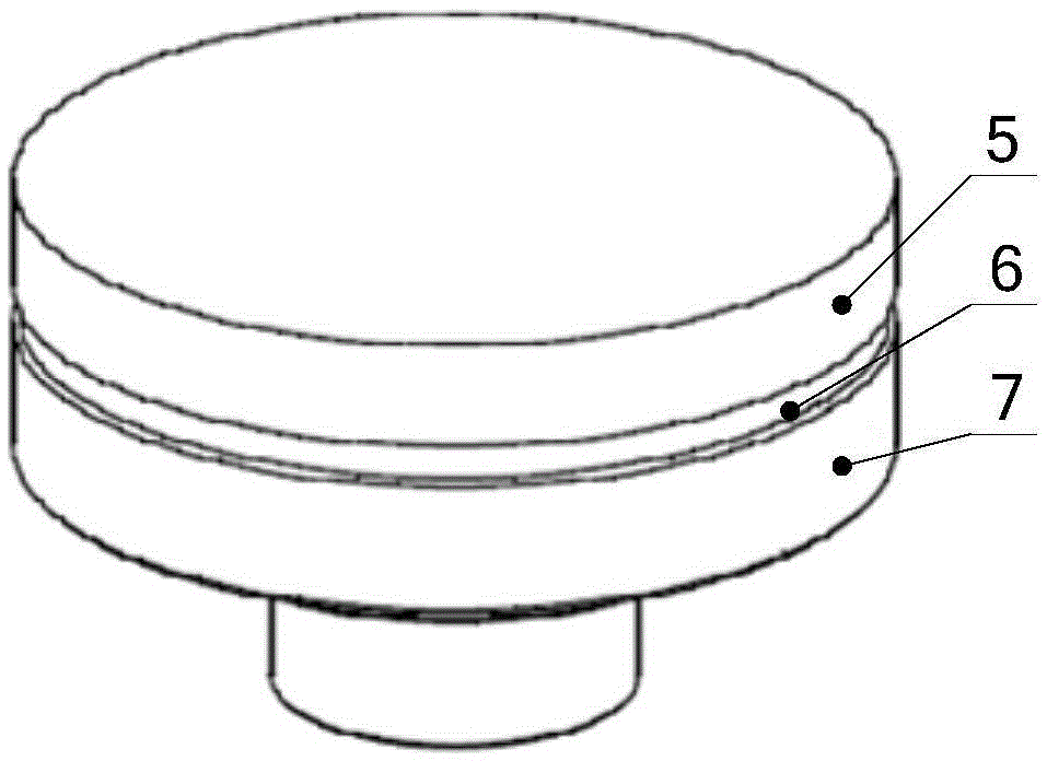
[0017] The clamping bushing 1 includes a circular ring structure 101 and a cylindrical structure 102. The side wall of the c...


PUM


Abstract

The invention belongs to the technical field of optical fabrication and provides a clamp controlling non-rotational symmetry errors for optical elements during polishing. The clamp aims to solve the problems that the polishing difficulty is high and the machining convergence efficiency is low in the prior art and comprises a clamping shaft sleeve, locking screws A, a one-dimensional translation table and a fixed base; the clamping shaft sleeve is fixed to the upper installation surface of the one-dimensional translation table, and the lower installation surface of the one-dimensional translation table is fixedly connected to the fixed base; the clamping shaft sleeve is coaxial with the fixed base, is of a flexible structure and is locked by the locking screws A. According to the invention, through monitoring to the magnitude and the directions of the non-rotational symmetry errors in the machining process, the offset of the optical elements can be adjusted in the directions of the errors correspondingly, the non-rotational symmetry errors can be corrected, and the machining efficiency can be improved. Through the simple, accurate and reliable clamping mode, the non-rotational symmetry errors of the optical elements in the classical polishing process can be effectively controlled.

Description

technical field [0001] The invention belongs to the technical field of optical manufacturing, and in particular relates to a jig for polishing optical elements for controlling non-rotational symmetry errors. Background technique [0002] For the classical polishing process that is widely used in the processing of optical components, the clamping of optical components in the processing process generally adopts the method of asphalt bonding, see the attached figure 1 , the optical element 5 is bonded to the aluminum disk 7 through pitch 6, and then the aluminum disk is installed on the rotary table of the processing machine tool to realize the coaxial positioning of the optical element and the workpiece axis of the machine tool. However, in the bonding process, the method of human eye alignment is often used, and the coaxiality between the optical element and the aluminum disc 7 is difficult to be accurately guaranteed, so that it is easy to cause non-rotational symmetry error...

Claims


Application Information

Patent Timeline
Patent Type & Authority Applications(China)
IPC IPC(8): B24B13/005
CPCB24B13/005
Inventor 王高文田伟马占龙杨怀江隋永新
Owner CHANGCHUN INST OF OPTICS FINE MECHANICS & PHYSICS CHINESE ACAD OF SCI
Why Eureka
Try Eureka