
Potable water lifesaving device

A life-saving device and portable technology, which is applied in the field of portable water life-saving devices, can solve problems such as the inability to calculate and control the delay time, and achieve the effects of improving rescue capabilities, low cost, and long distance

Inactive Publication Date: 2016-04-06
尹仕杰
View PDF7 Cites 0 Cited by
  • Summary
  • Abstract
  • Description
  • Claims
  • Application Information

AI Technical Summary

Problems solved by technology

In principle, the method of delayed inflation is adopted, but in actual operation, there is a problem that the delay time cannot be calculated and controlled

Method used


Image

  • Potable water lifesaving device
  • Potable water lifesaving device

Examples


Embodiment 1

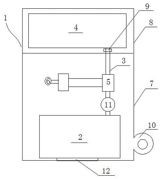
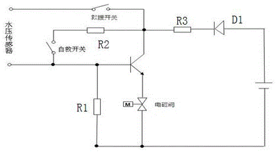
[0018] Such as figure 1 , 2 A portable water lifesaving device shown includes a portable box body 1, a compressed gas tank 2 arranged in the box body, and a life buoy 4 to be inflated connected to the compressed gas tank 2 through a connecting pipe 3, and a solenoid valve is arranged on the connecting pipe 3 5. The solenoid valve 5 is electrically connected to the switch control circuit, the switch control circuit includes a power supply, the solenoid valve 5 connected to the negative pole of the power supply and one end of the resistor R1, the other end of the resistor R1 is connected to the base of the triode, and the emitter of the triode is connected to the electromagnetic At the other end of the valve, the anode of the power supply, diode D1 and resistor R3 are connected in series to the collector of the triode, one end of the self-rescue switch is connected to the base of the triode, the other end is connected to the collector of the triode through the resistor R2, and o...

Embodiment 2

[0026] The switch control circuit includes a power supply and three switch circuits, one of which is connected to the control module and the solenoid valve (5) through the water pressure sensor (6), one is connected to the control module and the solenoid valve (5) through the wireless receiving module, and one is connected to the solenoid valve (5). It is directly connected with the solenoid valve (5) through the manual switch, and the solenoid valve is energized and opened by starting any path of the switch control circuit, and the compressed gas in the compressed gas tank is released to inflate the life buoy to be inflated.

[0027] In the design scheme of embodiment 2, more consideration is given to that when any road fails, other roads can be used to inflate the lifebuoy, and the cost does not increase too much, but the practicability will be stronger and the safety factor will be higher.

[0028] The invention is capable of self-rescue and long-distance rescue, and has pow...


PUM


Abstract

The invention discloses a potable water lifesaving device. The potable water lifesaving device comprises a portable tank body, a compressed air tank arranged in the tank body and a to-be-inflated lifesaving buoy connected with the compressed air tank through a connecting pipe. An electromagnetic valve is arranged on the connecting pipe. The electromagnetic valve is electrically connected with a switch control circuit. The electromagnetic valve is finally electrified and started by turning on a self-rescue switch or a rescue switch of the switch control circuit, and compressed air in the compressed air tank is released to inflate the to-be-inflated lifesaving buoy. The potable water lifesaving device can be projected by hands or machines conveniently and can be projected farther, and rescue and self-rescue can be achieved. The potable water lifesaving device is small in size, convenient to carry, low in cost and suitable for civil use. Rescue and self-rescue are conducted more flexibly through the switch control mode. The compressed air tank can perform inflation and air replenishing, and the application is safer. The lifesaving buoy can be separated from a main body after being inflated through a lifesaving buoy separation device, the weight of the lifesaving buoy is reduced and the rescue ability of the lifesaving buoy is improved. The potable water lifesaving device can be stored for a long time and is more stable than chemical medicine inflation systems in markets, so that the application is safe.

Description

technical field [0001] The invention relates to a lifesaving device, in particular to a portable water lifesaving device. Background technique [0002] About 1,050 people die from drowning every day in the world, and about 388,000 people die from drowning every year. Most of the drowning people were far away from the shore and could not throw the life buoy. When the rescuers arrived, they had already drowned. This is mainly because the life buoy is not easy to carry after it is inflated, or even if the inflated life buoy is carried, it cannot be thrown far or is still inaccurate due to the resistance of the inflated life buoy, and it is difficult to throw it to the rescued person. posed an obstacle. [0003] Some rescue devices can only be carried around or use unstable chemicals, high cost, and are not suitable for civilian use. The applicant has designed a mechanical time-delay lifebuoy and an electronically controlled portable self-inflating lifebuoy to solve the above...

Claims


Application Information

Patent Timeline
Patent Type & Authority Applications(China)
IPC IPC(8): B63C9/23B63C9/18
CPCB63C9/18B63C9/23
Inventor 尹仕杰
Owner 尹仕杰
Learn More