Conveying device for special hinge pins of motorcycle

A transmission device, motorcycle technology, applied in the direction of conveyors, conveyor objects, transportation and packaging, etc., can solve the problems of high equipment cost, high labor intensity, etc.

Active Publication Date: 2016-04-06
邳州市景鹏创业投资有限公司
View PDF6 Cites 0 Cited by
  • Summary
  • Abstract
  • Description
  • Claims
  • Application Information

AI Technical Summary

Problems solved by technology

[0003] The present invention intends to provide a special pin transmission device for motorcycles to solve the problems of high labor intensity or high equipment cost in the existing pin transmission technology

Method used


Image

  • Conveying device for special hinge pins of motorcycle
  • Conveying device for special hinge pins of motorcycle

Examples


Embodiment Construction

[0011] The present invention will be described in further detail below by means of specific embodiments:

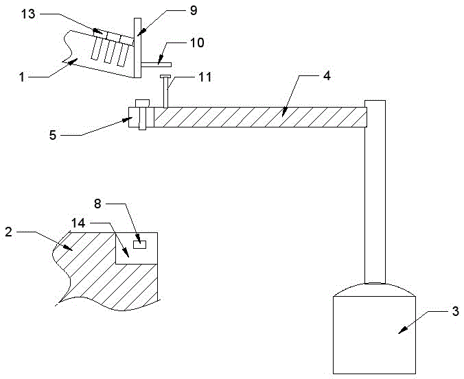
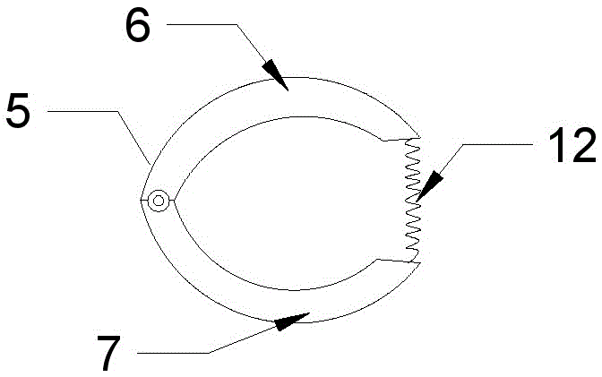
[0012] The reference signs in the accompanying drawings of the description include: pin shaft transmission chute 1, processing table 2, cylinder 3, support shaft 4, jaw 5, first jaw 6, second jaw 7, magnet 8, closing door 9 , Support plate 10, push piece 11, extension spring 12, bearing pin 13, through groove 14.

[0013] The embodiment is basically as attached figure 1 Shown: the transmission device of the pin shaft dedicated to motorcycles, including the pin shaft 13 transmission chute 1, the transmission mechanism and the processing table 2, the groove width of the pin shaft 13 transmission chute 1 is smaller than the diameter of the larger end of the pin shaft 13 and larger than the pin shaft 13 The diameter of the smaller end of the shaft 13, through the above settings, can keep the larger end of the pin shaft 13 facing upward during the transmission process, so tha...


PUM


Abstract

The invention discloses a conveying device for special hinge pins of a motorcycle. The conveying device comprises a hinge pin conveying sliding groove, a transferring mechanism and a machining table. The hinge pin conveying sliding groove is arranged obliquely. The output end of the hinge pin conveying sliding groove is slidably connected with a sealing door. The transferring mechanism comprises an air cylinder, a supporting shaft and an iron clamping jaw used for clamping the hinge pins. One end of the supporting shaft is perpendicular to the air cylinder and is connected to a piston rod of the air cylinder. The other end of the supporting shaft is hinged to the clamping jaw. The clamping jaw is located under the output end of the hinge pin conveying sliding groove. The supporting shaft is further provided with a pushing piece used for pushing the sealing door. A through groove used for containing the clamping jaw is formed in the machining table. Magnets used for attracting the clamping jaw are arranged on the two side walls of the through groove. By the adoption of the scheme, the problem that according to an existing hinge pin conveying technique, the labor intensity is high or the equipment cost is high is solved.

Description

technical field [0001] The invention relates to the field of pin shaft processing, in particular to a transmission device for a special pin shaft for motorcycles. Background technique [0002] The pin is T-shaped with a large top and a small bottom, and is used to fasten the gear transmission shaft and the connecting plate. The pin has a small volume, the diameter of the larger end is 0.3 cm, and the diameter of the smaller end is 0.2 cm. When organizing the pin shaft and other components, it is necessary to transfer the pin shaft to the processing table one by one for operation. At present, there are generally two methods for the transmission of pin shafts. One is manual transmission, that is, the pin shafts are taken out from the pin shaft pile one by one and placed on the processing table manually. This method is labor-intensive, and the other method is It is completed by numerical control equipment. Although this equipment has high efficiency, the price and cost are too...

Claims


Application Information

Patent Timeline
Patent Type & Authority Applications(China)
IPC IPC(8): B65G47/90B65G11/20
CPCB65G11/203B65G47/901B65G2201/0214
Inventor 陈文斌
Owner 邳州市景鹏创业投资有限公司
Why Eureka
Try Eureka