Drill bushing assembly and novel drill box for automatic anchor protection operation

A technology for drill sleeves and drill boxes, which is applied in the direction of drill pipes, casings, and drill pipes. It can solve problems such as the single function of anchoring equipment, the influence of the normal use of the drill box, and the time-consuming replacement process, so as to achieve lifting, maintenance and normal work. High efficiency, reduced labor workload, and convenient disassembly and assembly of drill pipes

Pending Publication Date: 2022-08-09
TAIYUAN INST OF CHINA COAL TECH & ENG GROUP +1
View PDF0 Cites 0 Cited by
  • Summary
  • Abstract
  • Description
  • Claims
  • Application Information

AI Technical Summary

Problems solved by technology

The traditional support process mainly relies on manual drilling and anchoring, which has defects such as single function of anchoring equipment, poor matching coordination, low operating efficiency, large number of people, and poor safety, so it is easy to cause serious imbalance in mining
[0003] At present, the intelligent anchoring machine is beginning to be developed and gradually replaces the traditional bolting machine. After testing, it is found that the following problems are prone to occur when using an ordinary drilling box for automatic anchoring operations, resulting in failure of the drilling box
[0004] (1) At present, the bolts commonly used in coal mines are damping bolts, and the tail is equipped with damping parts. During the fastening process of the bolt, it is judged whether the torque of the bolt is fastened in place by whether the damping parts are twisted. Parts fall off into the drill sleeve, with the increase of the number of operations, the accumulated damping parts will affect the normal use of the drill box
[0005] (2) According to the technical specifications and standards of bolt support, the orientation of the anchor trays that have completed the work must be consistent. During the stirring and fastening process of the anchor bolts in the ordinary drilling box, the trays will rotate with the anchor bolts, and the orientations will be randomly distributed. Workers need to correct the orientation of the pallets one by one, which requires a large amount of labor
[0006] (3) According to the hexagonal shape of the anchor rod, the contact surface between the inside of the drill sleeve and the anchor rod of the ordinary drill box is designed as an inner hexagon to limit the anchor rod. However, during the process of replacing the drill rod, the limit surface must be squared Can be installed, due to the low illumination environment underground, the replacement process takes a long time

Method used


Image

  • Drill bushing assembly and novel drill box for automatic anchor protection operation
  • Drill bushing assembly and novel drill box for automatic anchor protection operation
  • Drill bushing assembly and novel drill box for automatic anchor protection operation

Examples


Embodiment 1

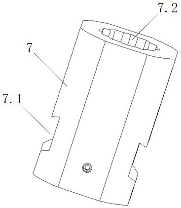
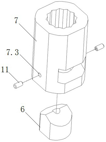
[0034] This embodiment provides a drill sleeve assembly for connecting the motor drive shaft 5 and the damping anchor rod 9, the top end is provided with a limit hole 7.1 for inserting the nut 9.1 at the bottom end of the damping anchor rod 9, and the symmetrical arrangement on both sides is useful The damping element escape hole 7.2 is inserted into the damping element escape hole 7.2 fixedly connected with the nut 9.1 at the bottom end of the damping anchor rod 9 for the damping element 10; the damping element escape hole 7.2 is communicated with the limit hole 7.1, and is provided with a damping element escape inclined surface inclined to the bottom end.

[0035] Further, the above-mentioned drill sleeve assembly includes a drill sleeve 7 and abutting column 6; the limit hole 7.1 and the damping member escape hole 7.2 are both provided on the drill sleeve 7, and the bottom end of the drill sleeve 7 is also provided with the limit hole 7.1 and damping The top surface and the ...

Embodiment 2

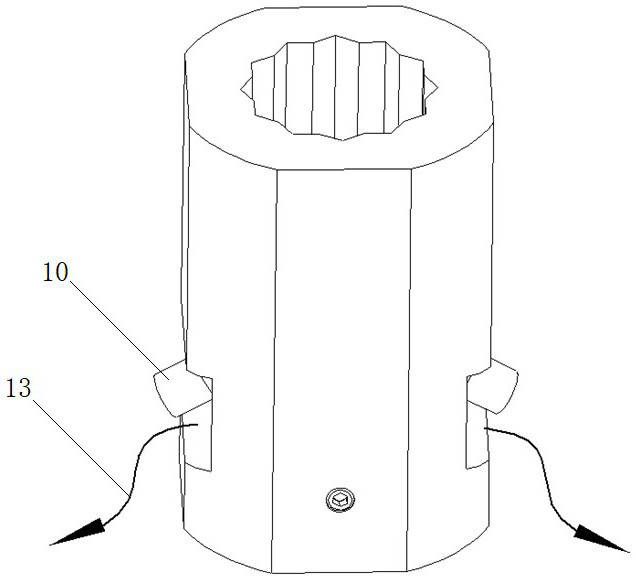
[0039] This embodiment provides a new type of drill box for automatic anchoring operation, including a drill box body 1, a drill box motor 2, a motor drive shaft 5, a damping member 10 and a damped anchor rod 9; a drill box motor 2 and a motor drive shaft 5 is installed on the drill box body 1, and the drill box motor 2 drives the motor drive shaft 5 to rotate; the motor drive shaft 5 and the damping anchor rod 9 are connected through the above drill sleeve assembly, and the serrations of the nut 9.1 on the damping anchor rod are fitted in the In the serration of the limit hole 7.1.

[0040] Further, the nut 9.1 on the damping anchor rod 9 is a hexagonal nut, and the limiting hole 7.1 of the drill sleeve 7 is a dodecahedral serrated hole.

[0041] Further, an anchor rod tray 8 is rotatably installed on the damping anchor rod 9; two tray clamping claws 4 are symmetrically arranged on both sides of the drilling box body 1, and the distance between the two tray clamping claws 4 i...


PUM


Abstract

The invention provides a drill bushing assembly and a novel drill box for automatic anchor protection operation, and belongs to the technical field of roadway supporting, and the drill box comprises a drill box body, a drill box motor, a motor transmission shaft, a damping piece, a damping type anchor rod, a drill bushing and an abutting column. Wherein the drilling box motor and the liquid distribution plate are mounted on the drilling box body, and the drilling sleeve is connected with the motor transmission shaft to transmit torque; the tray clamping claws are symmetrically assembled on the drilling box body in a detachable mode and can limit the anchor rod tray. The drill bushing is provided with the damping piece disengaging hole in a double-inclined-face mode, the damping piece can be disengaged through the damping piece disengaging hole in the anchoring process, the drill bushing is in a multi-face limiting mode, and therefore the drill rod is more convenient to disassemble. According to the drilling box, the reliability is improved, the service life of the drilling box is prolonged, the working safety and efficiency are improved while the labor intensity of automatic anchor protection operation is reduced, and the automation and standardization progress of the anchor protection operation is promoted.

Description

technical field [0001] The invention belongs to the technical field of roadway support, and specifically discloses a drill sleeve assembly and a novel drill box for automatic anchoring operation. Background technique [0002] The underground mining method is the main mining method of coal resources in China. The support working face is a densely distributed workplace for mine operators, and the support work is carried out immediately after the tunnel is excavated, and the operating environment is also relatively harsh. The traditional supporting process mainly relies on manual drilling and anchoring. There are defects such as single function of anchoring equipment, poor matching coordination, low operation efficiency, many people, and poor safety. Therefore, it is easy to cause serious mining imbalance. [0003] At present, the intelligent anchoring machine has begun to be developed and gradually replaced the traditional bolting machine. It is found through experiments that ...

Claims


Application Information

Patent Timeline
Patent Type & Authority Applications(China)
IPC IPC(8): E21D20/00E21B17/03E21D21/00
CPCE21D20/00E21B17/03E21D21/008
Inventor 吕继双张东宝米豪鼎刘长龙孔令志李杰苏杭王焱民裴明尧贾运红焦晓峰任晓文朱振天米雄伟
Owner TAIYUAN INST OF CHINA COAL TECH & ENG GROUP
Why Eureka
Try Eureka