Cloth ironing machine

A technology for ironing machine and cloth, applied in spray/jet textile material treatment, heating/cooling fabric, textile and papermaking, etc., can solve the problems of reduced profit, low work efficiency, large power consumption, etc., to improve ironing work Efficiency, improved ironing effect, time saving effect

Inactive Publication Date: 2016-04-06
SHENGZHOU YIHAI MOTOR PARTS FACTORY
View PDF8 Cites 42 Cited by
  • Summary
  • Abstract
  • Description
  • Claims
  • Application Information

AI Technical Summary

Problems solved by technology

[0003] There are two types of ironing machines in the prior art. One is that the upper mold is fixed on the frame, and there is an operating platform under the corresponding lower mold. The lower mold stretches up against the upper mold for heating and shaping, and the workers need to stand all the time to operate, the work efficiency is low and the labor intensity is high; the other is to use a high-power motor to press the upper mold to the lower mold with a hydraulic press, and spray High-temperature steam is used to heat and shape the fabric, which consumes a lot of power
Moreover, the finishing machine directly irons the fabric, and the ironing process is fast, and the ironing may be completed before the ironing is smooth, and the desired effect cannot be achieved. If the ironing is repeated, the energy consumption is large and time-consuming
During the steam heating process, the hot steam is easy to condense inside the fabric. If it is not ventilated and dried later, the fabric is prone to mildew and deterioration, which will bring losses to home textile enterprises and reduce profits.
After the fabric is ironed, it is generally collected directly. At this time, the fabric is not completely cooled, and it is easy to regenerate wrinkles during the stacking and placement, which is not conducive to the next processing

Method used


Image

  • Cloth ironing machine
  • Cloth ironing machine
  • Cloth ironing machine

Examples


Embodiment Construction

[0020] The preferred embodiments of the present invention will be described in further detail in conjunction with the accompanying drawings.

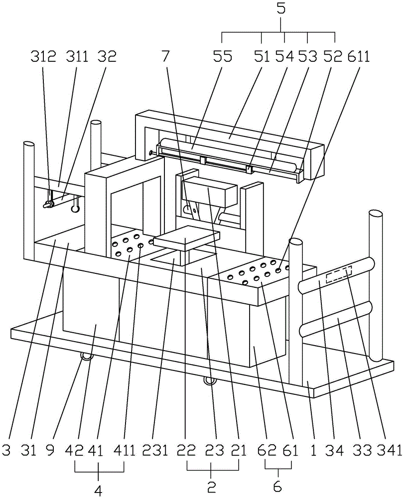
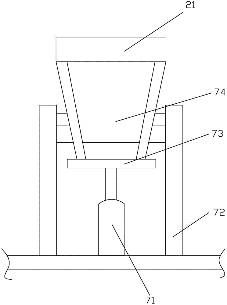
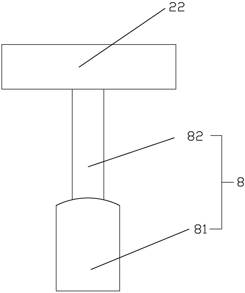
[0021] Such as Figure 1-6 As shown, a cloth ironing machine includes a frame 1, an ironing mechanism 2 and a transmission mechanism 3, and also includes a preheating mechanism 4, a sterilizing mechanism 5 and a drying mechanism 6, and the preheating mechanism 4 is located in the ironing mechanism 2 on the feed side, the sterilizing mechanism 5 is located on the discharge side of the ironing mechanism 2. The conveying mechanism 3 includes a feeding platform 31, a cloth releasing roller 32 and a cloth rolling roller 33, the cloth releasing roller 32 is located above the discharging platform 31, and hanging rods 311 are provided on both sides of the discharging platform 31, and the The hanging rods 311 are respectively provided with at least two pairs of hanging rings 312 . The hanging rings 312 are slidingly connected with the hanging r...


PUM


Abstract

The invention mainly discloses a cloth ironing machine. The technical scheme is that the cloth ironing machine comprises a rack, an ironing mechanism, a conveying mechanism, a preheating mechanism, a sterilization mechanism and a drying mechanism, wherein the conveying mechanism comprises a putting table, cloth putting rollers and a cloth reeling roller, the putting table is provided with hanging rings, two ends of the cloth putting rollers are respectively hung on the hanging rings, one side of the cloth reeling roller is provided with a cooling roller, the ironing mechanism comprises an upper press mould, a lower press mould and an ironing table, the lower sides of the upper press mould and the lower press mould are respectively provided with a first transmission mechanism and a second transmission mechanism for driving the upper press mould and the lower press mould to be in force fit, the preheating mechanism comprises a preheating plate provided with steam holes and a water tank with an electric heater, the sterilization mechanism comprises a lamp base, a lamp holder and an ultraviolet tube with a cleaning device, the drying mechanism comprises a drying plate provided with air outlets and a warm air chamber provided with a warm air machine, and sliding wheels are arranged below the rack. The cloth ironing machine has the advantages of good ironing effect, shaping in one step, high work efficiency and less energy consumption.

Description

technical field [0001] The invention relates to the field of textile machinery, in particular to a cloth ironing machine. Background technique [0002] Fabric ironing is an important part of home textile production. It is a process of ironing the uneven parts of the fabric with high temperature or steam to achieve a smoother appearance and a more three-dimensional and more beautiful appearance. Ironing is mainly to use the thermoplasticity of textile fibers to change its degree of expansion and maintain a certain shape to make up for the defects caused in the weaving or sewing process. Some fabrics require ironing before proceeding to the next step. [0003] There are two types of ironing machines in the prior art. One is that the upper mold is fixed on the frame, and there is an operating platform under the corresponding lower mold. The lower mold stretches up against the upper mold for heating and shaping, and the workers need to stand all the time to operate, the work e...

Claims


Application Information

Patent Timeline
Patent Type & Authority Applications(China)
IPC IPC(8): D06C7/02D06C15/10D06B1/02A61L2/10
CPCA61L2/10D06B1/02D06C7/02D06C15/10
Inventor 陈意
Owner SHENGZHOU YIHAI MOTOR PARTS FACTORY
Why Eureka
Try Eureka