Textile fabric cutting machine

A cloth cutting machine and textile technology, applied in the cutting of textile materials, textile and paper making, and sending objects, etc., can solve the problems of affecting the quality of cloth, large manual labor, and low level of automation, so as to reduce the amount of manual operations, Reduced operating time and high degree of automation

Inactive Publication Date: 2016-04-06
SHENGZHOU YIHAI MOTOR PARTS FACTORY
View PDF0 Cites 4 Cited by
  • Summary
  • Abstract
  • Description
  • Claims
  • Application Information

AI Technical Summary

Problems solved by technology

The cloth cutting machine in the prior art only uses one cutting knife. When the cutting knife is damaged during the cutting process with the cloth, the machine needs to be stopped and a new cutting knife must be installed manually, which is troublesome to replace, wastes time, and reduces Cloth cutting efficiency
During the cloth cutting process, the operator needs to install the cloth on the winding mechanism or pull the part of the cloth to be cut to the cutting mechanism. Once the cutting is completed, the operator needs to rewind the following cloth to the winding mechanism or The place to be cut in the fabric is pulled to the cutting mechanism, and the operator pulls the fabric many times, resulting in a large amount of manual labor, low automation level, and low work efficiency
Some cloth cutting machines are not equipped with a cloth receiving device, and the cut cloth falls directly to the ground and is piled up randomly, polluting the cloth and affecting the quality of the cloth

Method used


Image

  • Textile fabric cutting machine
  • Textile fabric cutting machine
  • Textile fabric cutting machine

Examples


Embodiment Construction

[0016] The preferred embodiments of the present invention will be described in further detail in conjunction with the accompanying drawings.

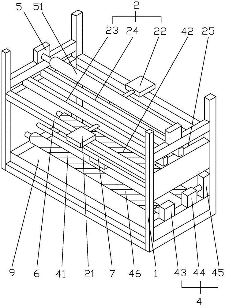
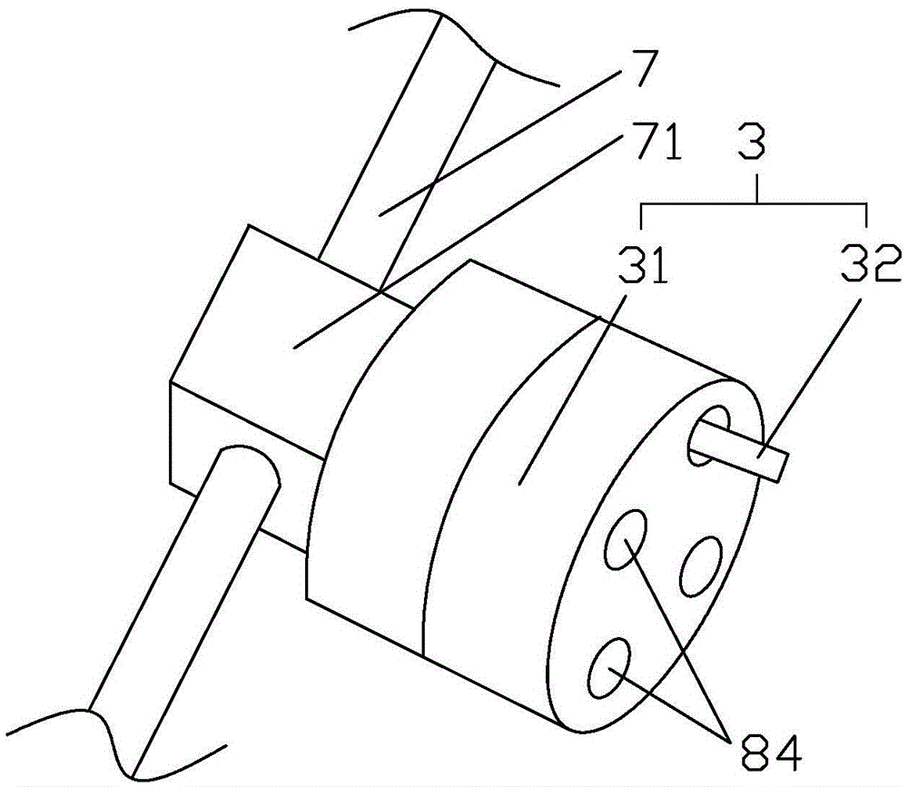
[0017] Such as Figure 1-4 As shown, a textile cloth cutting machine includes a frame 1, a cloth clamping mechanism 2, a cutter 3 and a transmission mechanism 4, and the cloth clamping mechanism 2, the cutter 3 and the transmission mechanism 4 are sequentially arranged on the on rack 1. The upper side of the frame 1 is provided with a support seat 5, and the support seat 5 is provided with a cloth releasing roller 51 for placing the cloth to be cut. Two fixed rods 6 are arranged on the lower side of the cloth releasing roller 51 on the frame 1 , and the cloth clamping mechanism 2 is located on the fixed rods 6 . The cloth clamping mechanism 2 includes a first hydraulic cylinder 21, a second hydraulic cylinder 22, and a first cloth clamping rod 23 and a second cloth clamping rod 24 respectively arranged on the piston rods of the first ...


PUM


Abstract

The invention mainly discloses a textile fabric cutting machine. The technical scheme is that the machine comprises a rack, a cloth clamping mechanism, a cutting device, and a transmission mechanism. The cloth clamping mechanism, the cutting device, and the transmission mechanism are arranged on the rack from top to bottom in sequence. The rack is horizontally provided with a rodless cylinder. The cutting device is on the rodless cylinder. The cutting device comprises an adapter base and at least two cloth cutters. The adapter base comprises a fixing portion and a moving portion. The moving portion is internally provided with a rotary disk, a stepping motor, and a mini cylinder. The fixing portion is internally provided with a first hole and a second hole. The cloth cutters are in the first hole. The cloth cutter is provided with a spring and a push rod. The second hole is provided with stop block cooperated with the push rod. The transmission mechanism is formed by a group of main rollers and auxiliary rollers. The lower side of the transmission mechanism is provided with a cloth placing frame. The machine can rapidly replace the cloth cutters, and automatically pulls cloth, and is high in automation degree, low in manual operation amount, and high in cutting efficiency.

Description

technical field [0001] The invention relates to the technical field of textile machinery, in particular to a textile cutting machine. Background technique [0002] Generally, the cloth is rolled up and placed with a cloth roller after it has just been woven into white blank or after printing and dyeing. The cloth is in the state of a whole piece. According to the specifications, the whole piece of fabric is cut according to the appropriate length to form a certain length and width of fabric, which is convenient for subsequent processing and use. The cloth cutting machine in the prior art only uses one cutting knife. When the cutting knife is damaged during the cutting process with the cloth, the machine needs to be stopped and a new cutting knife must be installed manually, which is troublesome to replace, wastes time, and reduces Cutting efficiency. During the cloth cutting process, the operator needs to install the cloth on the winding mechanism or pull the part of the c...

Claims


Application Information

Patent Timeline
Patent Type & Authority Applications(China)
IPC IPC(8): D06H7/02B65H35/06
CPCD06H7/02B65H35/06B65H2701/174
Inventor 陈意
Owner SHENGZHOU YIHAI MOTOR PARTS FACTORY
Why Eureka
Try Eureka