Balance weight buffering type height limiting frame

A technology of weights and height-limiting rods, which is applied in the direction of restricting traffic, roads, road safety devices, etc., can solve the problems of not attracting the driver's attention, easily bumping into the height-limiting frame, and increasing maintenance costs, so as to ensure personal safety and Effects of public facility safety, reduction of maintenance and repair costs, and reduction of accident rate

Inactive Publication Date: 2016-04-06
吕云祥
0 Cites 14 Cited by

AI-Extracted Technical Summary

Problems solved by technology

[0002] In roads, culverts, bridges and railways running through the road, in order to ensure the safety of vehicles, protect public facilities, and prevent vehicles with high heights from damaging bridges and other facilities on the road surface, a height limit will be set up at the corresponding position. To indicate the height limit, ordinary height limiters fix two columns on both sides of the road, and connect them to the two columns through a horizontal height limit rod, but this kind of height limiter has many inconveniences: the height limiter usually...

Method used

Adhere to the sponge rubber layer on the impact surface of the height limit pole 1, the sponge rubber layer is elast...

Abstract

The invention relates to a balance weight buffering type height limiting frame, and belongs to the field of highway facilities. The balance weight buffering type height limiting frame comprises stand columns separately standing on the two sides of a highway, two guide rails are fixed to the upper ends of the two stand columns respectively and are parallel, and a height limiting rod is arranged in the two guide rails. A first pulley and a second pulley are arranged on the outer sides of the guide rails respectively, and the first pulley is located in front of the original position of the height limiting rod. One end of a steel cable is fixed to the height limiting rod, and the other end of the steel cable winds across the first pulley and the second pulley and then is connected with a balance weight. The balance weight is arranged in a deep well below the second pulley, and the gravity of the balance weight is used for providing buffer for the height limiting frame, so that direct collision between vehicles and the height limiting frame is avoided, damage to the height limiting frame and the vehicles is reduced, and personal safety of drivers is guaranteed.

Application Domain

Technology Topic

Image

  • Balance weight buffering type height limiting frame
  • Balance weight buffering type height limiting frame

Examples

  • Experimental program(1)

Example Embodiment

[0019] Embodiments of the present invention are further described below in conjunction with accompanying drawings:
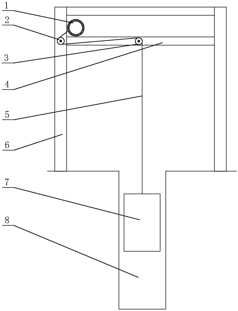
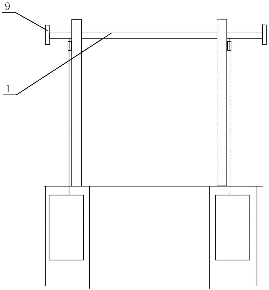
[0020] like figure 1 and figure 2 As shown, the pendant buffer type height-limiting frame of the present invention includes uprights 6 separated on both sides of the road, and guide rails are respectively fixed at the upper ends of the two uprights 6, and the two guide rails are parallel. The No. 1 pulley 2 and the No. 2 pulley 3, wherein the No. 1 pulley 2 is in front of the original position of the height-limiting pole 1, and one end of the steel cable 5 is fixed on the height-limiting pole 1, and the other end goes around the No. 1 pulley 2 and the No. 2 pulley respectively 3 connects the weight 7, and the weight 7 is placed in the deep well 8 below the No. 2 pulley 3.
[0021] Working principle and process:
[0022] Under normal conditions, the gravity of the weight 7 pulls the height limiting rod 1 to the front end (initial position) of the slide rail 4 through the steel cable 5. When a vehicle hits the height limiting rod 1, the height limiting rod 1 moves upward on the slide rail 4 After sliding, since the height limit rod 1 is connected with the weight 7, the stroke of the height limit rod 1 is the stroke of the weight 7 rise, and the gravity of the weight 7 provides a pulling force to the height limit rod 1 to prevent the height limit rod 1 from moving backward. When driving, the driver will also take braking measures after he realizes that he hits the height limit pole 1. The weight 7 makes the height limit pole 1 have a certain buffering effect, avoiding the damage caused by the rigid impact. After the vehicle withdraws, the height limit pole 1 Return to original position again under weight 7 effect.
[0023] The length of the height limit rod 1 is greater than the distance between the two columns 6, because the vehicle generally does not just hit the center of the height limit rod 1 during the collision, and the height limit rod 1 must have a relatively long sliding distance during the sliding process. Some, when one end of the height limit rod 1 reaches the rear limit position, the other end may still be in the original position, therefore, the height limit rod 1 should have enough travel to provide buffering.
[0024] In order to prevent the height-limiting rod 1 and the slide rail 4 from being worn out due to long-term sliding, rollers are set on the height-limiting rod 1, and the height-limiting rod 1 contacts with the slide rail 4 through the rollers, which effectively reduces the wear of the height-limiting rod 1 and the slide rail 4 , prolonging the service life of the limit-elevator.
[0025] The roller is a free type roller, and the roller can slide axially on the height limiting rod 1.
[0026] The sponge rubber layer is attached to the impact surface of the height limiting pole 1, and the sponge rubber layer is elastic and not easy to be damaged, and the damage degree of the vehicle and the height limiting pole 1 can be reduced during impact.
[0027] Height-limiting bar 1 two ends fix limit block 9, and the height of limit block 9 is greater than the gap of slide rail 4, prevents height-limiting bar 1 from extracting out from slide rail 4.
[0028] The slide rail 4 is a closed slide rail 4, which prevents the height limit rod 1 from breaking away from the slide rail 4 from the top due to excessive impact.
[0029] In order to ensure that the height-limiting rod 1 has enough buffer travel, the depth of the deep well 8 will be greater than the length of the slide rail 4.

PUM

no PUM

Description & Claims & Application Information

We can also present the details of the Description, Claims and Application information to help users get a comprehensive understanding of the technical details of the patent, such as background art, summary of invention, brief description of drawings, description of embodiments, and other original content. On the other hand, users can also determine the specific scope of protection of the technology through the list of claims; as well as understand the changes in the life cycle of the technology with the presentation of the patent timeline. Login to view more.

Similar technology patents

Low friction chain

ActiveUS20080020882A1Reduce wearCombustion efficiency be improveDriving chainsEdge surfaceLow friction
Owner:TSUBAKIMOTO CHAIN CO

Insulator cleaning robot

Owner:STATE GRID INTELLIGENCE TECH CO LTD

Classification and recommendation of technical efficacy words

  • Extended service life
  • Reduce wear

Power system with enhanced thermodynamic efficiency and pollution control

InactiveUS6918253B2Reduce equipment costsReduce wearSteam generation using pressureSteam useCondensed waterPressure range
Owner:THERMOENERGY POWER SYST

Denture

InactiveUS6139322ASuperior physical and aesthetic characteristicReduce wearImpression capsArtificial teethInterpenetrating polymer networkDentures
Owner:DENTSPLY RES DEVMENT
Why Eureka
Try Eureka