Cutting tool wear detection method

A cutting tool and detection method technology, applied in the field of cutting tools, can solve problems such as tool wear error

Active Publication Date: 2016-04-06
CHINA RAILWAY CONSTR HEAVY IND
View PDF6 Cites 8 Cited by
  • Summary
  • Abstract
  • Description
  • Claims
  • Application Information

AI Technical Summary

Problems solved by technology

However, due to the influence of the installation method, there is a large error in the amount of tool wear detected by the existing online detection method

Method used


Image

  • Cutting tool wear detection method
  • Cutting tool wear detection method
  • Cutting tool wear detection method

Examples


Embodiment Construction

[0038] The implementation of the present invention will be described in detail below in conjunction with the accompanying drawings and examples, so as to fully understand and implement the process of how to apply technical means to solve technical problems and achieve technical effects in the present invention. It should be noted that, as long as there is no conflict, each embodiment and each feature in each embodiment of the present invention can be combined with each other, and the formed technical solutions are all within the protection scope of the present invention.

[0039] Also, in the following description, for purposes of explanation, numerous specific details are set forth in order to provide a thorough understanding of embodiments of the invention. It will be apparent, however, to one skilled in the art that the present invention may be practiced without the specific details or in the particular manner described.

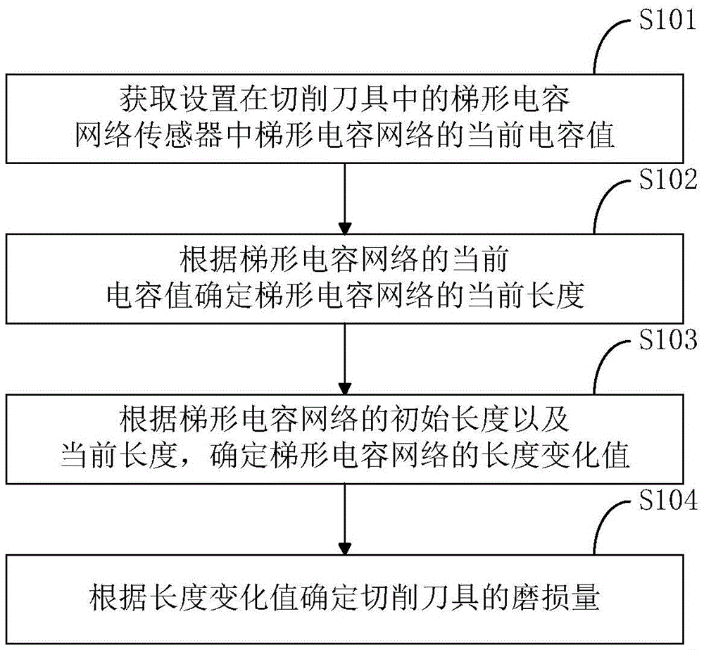
[0040] In addition, the steps shown in the flow dia...


PUM


Abstract

The invention discloses a cutting tool wear detection method. The method comprises a step of determining a capacitance value in which the current capacitance value of a ladder-shaped capacitor network in a ladder-shaped capacitor network sensor arranged in the cutting tool is acquired, a step of determining the current length of the capacitor network in which the current length of the ladder-shaped capacitor network is determined according to the current capacitance value of the ladder-shaped capacitor network, and a step of determining the wear amount in which the length change value of the ladder-shaped capacitor network is determined according to the initial length and the current length of the ladder-shaped capacitor network and the wear amount of the cutting tool is determined according to the length change value. The method of the invention can determine the wear amount of the cutting tool more accurately, and in the case of need, the wear shape of the cutting tool can be determined through configuring multiple sensors.

Description

technical field [0001] The invention relates to the technical field of cutting tools, in particular to a method for detecting the wear of cutting tools. Background technique [0002] Shield tunneling machine (referred to as shield machine) is a large-scale equipment for tunnel and subway construction, and it is a kind of cutting tool equipment. In the construction of the shield machine, the cutter is one of the most important tools in the excavation process. Before the cutter reaches the wear limit, the cutter must be replaced, otherwise it may cause disastrous engineering accidents. Therefore, the ability to accurately check the tool wear of the shield machine is directly related to whether the tunnel construction can be carried out normally. [0003] At present, the detection methods for the tool wear of the shield machine mainly include the shutdown inspection method, the threshold detection method, the tunneling parameter estimation method, and the online detection meth...

Claims


Application Information

Patent Timeline
Patent Type & Authority Applications(China)
IPC IPC(8): G01B7/00G01B7/06
CPCG01B7/00G01B7/001G01B7/08
Inventor 程永亮暨智勇夏毅敏兰浩薛静李建芳
Owner CHINA RAILWAY CONSTR HEAVY IND
Why Eureka
Try Eureka