High-precision temperature and pressure sensor

A technology of temperature, pressure and sensors, which is applied in the field of sensors, can solve the problems of temperature difference between the actual temperature, inaccurate measurement results, and low production efficiency, and achieve the effect of less pressure loss, good measurement effect and uniform force

Inactive Publication Date: 2016-04-06
WUHAN FINEMEMS
View PDF9 Cites 13 Cited by
  • Summary
  • Abstract
  • Description
  • Claims
  • Application Information

AI Technical Summary

Problems solved by technology

[0003] In the prior art, patents CN102435378A and CN202267563U provide a class of temperature and pressure sensors for measuring the pressure of the target fluid. The problems of this type of sensor are: the heat conduction of the measured medium to the temperature and pressure sensor needs to go through various Conduction of the medium—first conduct to the metal diaphragm, so that the temperature of the metal diaphragm changes, and then conduct from the metal diaphragm to the silicone oil, so that the temperature of the silicone oil changes, and finally make the silicone oil conduct to the temperature sensor, due to the long heat conduction process, There are many conductive media, so the heat loss is greater, and there is a temperature difference between the measured medium temperature and the actual temperature, and the measurement result is inaccurate
[0004] Patent CN201000367Y needs to install adjacent pressure sensitive cores, pressure strain gauges and temperature sensors in a narrow space. Although these sensors have high precision, they are difficult to process and require high process precision, resulting in high production costs and low production efficiency.
The patent CN201795879U has high precision, but the sealing performance must be guaranteed by the potting process, but the potting process itself is complicated and time-consuming, so the production efficiency is low, and the sealing performance of the product cannot be fully guaranteed

Method used


Image

  • High-precision temperature and pressure sensor
  • High-precision temperature and pressure sensor
  • High-precision temperature and pressure sensor

Examples


Embodiment Construction

[0041] The present invention will be further improved in conjunction with the accompanying drawings and embodiments below.

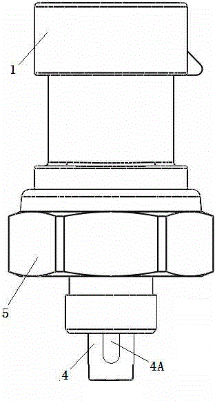
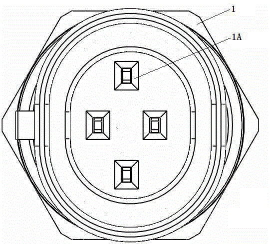
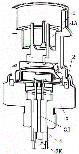
[0042] Such as Figure 1 to Figure 4 As shown, a high-precision temperature and pressure sensor includes a terminal button 1 with a pin 1A, a TO assembly 3, and a housing 5. The terminal button 1 is sealed with the housing 5 and is provided with interconnected capacitors on both sides of the sealing surface. The end of the shell 5 away from the end button 1 is provided with a through hole communicating with the cavity, the TO assembly 3 is located in the cavity, and the TO assembly 3 includes a TO plate 3I that seals the opening of the cavity on the shell 5, and the end button The PCB board 3H soldered to pin 1A on 1 (in this embodiment, the PCB board 3H is a flexible circuit board) and thermistor 3K, the PCB board 3H is arranged on the top surface of the TO board 3I, and the TO board 3I is provided with a thermistor connecting rod 3B (there are two the...


PUM


Abstract

The present invention relates to a temperature and pressure sensor which comprises a terminal with pins, a TO assembly and a shell. The terminal and the shell are connected in a sealed way, and two sides of a sealed surface are provided with cavity in mutual communication. One end of the shell far from the terminal is provided with a through hole which is communicated with the cavities. The T0 assembly is arranged in the cavity and comprises a TO plate which seals the cavity opening in the shell, a PCB which is connected to the pins in the terminal, and a thermistor. The PCB is arranged at the top surface of the TO plate which is provided with a thermistor wire connection rod and a pressure measuring through hole. One end of the thermistor wire connection rod extends downward into the through hole and is connected to the thermistor, and the other end goes through the PCB and is connected to the PCB. The PCB is connected to a sensitive device which comprises a pressure chip. The pressure chip just faces the pressure measuring through hole and goes through the bottom of the pressure measuring through hole to seal the pressure measuring through hole. The temperature and pressure sensor has the advantages of high measurement accuracy, simple structure, easy processing, low cost, and small size.

Description

technical field [0001] The invention belongs to the field of sensors and relates to a high-precision temperature and pressure sensor. Background technique [0002] The temperature and pressure sensor is an integrated sensor that can measure the medium pressure and temperature at the same point at the same time. Temperature and pressure sensors are suitable for occasions where the temperature of the medium is measured while measuring the pressure, for example—with the development of automobile automation and industrial automation technology, the application of gas rail systems in automobiles is becoming more and more common, and the gas is injected through the valve in the system The output pressure and temperature are fed back to the controller to control the opening degree of the valve, and temperature and pressure sensors need to be installed in the system to collect corresponding data. In addition, temperature and pressure sensors are required in other industrial fields ...

Claims


Application Information

Patent Timeline
Patent Type & Authority Applications(China)
IPC IPC(8): G01D21/02
Inventor 刘胜杨军王小平张雪峰
Owner WUHAN FINEMEMS
Why Eureka
Try Eureka