Supercharge Your Innovation With Domain-Expert AI Agents!

Laser oscillator

A laser oscillator and area technology, applied in the direction of lasers, laser components, laser components, etc., can solve problems such as difficulty in suppressing scattered light, complex structure, and decreased laser output

Inactive Publication Date: 2016-04-06
FANUC LTD
View PDF8 Cites 2 Cited by
  • Summary
  • Abstract
  • Description
  • Claims
  • Application Information

AI Technical Summary

Problems solved by technology

[0003] However, since the laser oscillator described in the above-mentioned patent document has a hole member, there is a problem that not only the structure becomes complicated, but also the hole member absorbs the laser light and the laser output decreases.
However, in this laser oscillator, since the periphery of the output mirror is coated with a non-reflective film, it is difficult to suppress the generation of scattered light

Method used


Image

  • Laser oscillator
  • Laser oscillator
  • Laser oscillator

Examples


Embodiment Construction

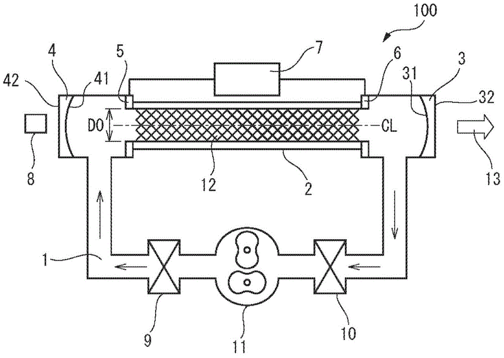
[0013] Below, refer to Figure 1 to Figure 6 Embodiments of the laser oscillator 100 according to the present invention will be described. figure 1 It is a diagram showing the overall configuration of the laser oscillator 100 according to the embodiment of the present invention. The laser oscillator 100 according to this embodiment is a high-output carbon dioxide gas laser oscillator that excites laser gas through a discharge tube through a laser gas as a medium.

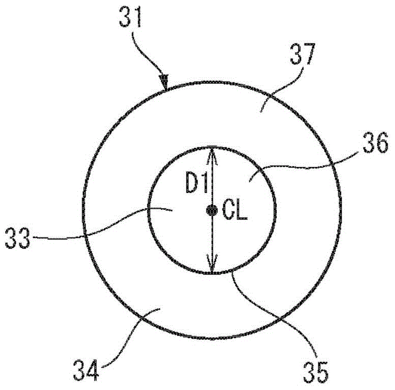
[0014] Such as figure 1 As shown, the laser oscillator 100 has: a gas flow path 1 for the circulation of laser gas; a discharge tube 2 communicated with the gas flow path 1; an output mirror 3 and a rear mirror disposed on both sides of the discharge tube 2 through the discharge tube 2 4; a power supply unit 7 that applies a voltage (discharge tube voltage) to electrodes 5 and 6 of the discharge tube 2; a sensor 8 that detects laser output; a heat exchanger 9 and 10 that cools the laser gas; and makes the laser ga...


PUM


Abstract

A laser oscillator includes a discharge tube having a discharge area in which laser gas is excited and an output coupler and a rear mirror respectively arranged at both sides of the discharge tube. A first coating material having first reflectance is stacked as a dielectric multilayer on a first area including a radial center portion of a surface of the output coupler, which faces the discharge area, and a second coating material having second reflectance higher than the first reflectance is stacked as a dielectric multilayer on a second area around the first area.

Description

technical field [0001] The present invention relates to a laser oscillator for oscillating laser light by exciting laser gas through a discharge tube. Background technique [0002] In general, the lower the mode number and the higher the dimensionality, the higher the quality (focusing property) of the laser beam output from the laser oscillator. A laser oscillator is known that suppresses laser oscillation in a high-order mode and performs laser oscillation in a low-order mode in consideration of this point. Such laser oscillators are disclosed, for example, in Japanese Patent No. 3313623, JP-A-2013-247260, and JP-A-2009-94161. In the laser oscillators described in these patent documents, an aperture is disposed between the output mirror and the rear mirror. The laser oscillator confines the diameter of laser light through the hole member, thereby suppressing laser oscillation in a higher-order mode, and suppressing generation of scattered light. [0003] However, since ...

Claims


Application Information

Patent Timeline
Patent Type & Authority Applications(China)
IPC IPC(8): H01S3/034H01S3/03
CPCH01S3/2232H01S3/0014H01S3/032H01S3/036H01S3/08063
Inventor 高实哲久
Owner FANUC LTD
Features
  • R&D
  • Intellectual Property
  • Life Sciences
  • Materials
  • Tech Scout
  • Unparalleled Data Quality
  • Higher Quality Content
  • 60% Fewer Hallucinations
Learn More