Adaptive charging control circuit and control method for switch charger

A technology for switching chargers and control circuits, which is applied to battery circuit devices, current collectors, circuit devices, etc., and can solve the problems of not knowing the current capability of the input power supply, the system not having the detection capability, and the power supply working.

Active Publication Date: 2016-04-06
NANJING SILERGY SEMICON TECH CO LTD
View PDF5 Cites 5 Cited by
  • Summary
  • Abstract
  • Description
  • Claims
  • Application Information

AI Technical Summary

Problems solved by technology

[0004] The second is that when the current capability of the input power supply is not known, for example, the non-standard adapter cannot be detected by the system to input the current limit value, or the system does not have the detection capability
Set

Method used


Image

  • Adaptive charging control circuit and control method for switch charger
  • Adaptive charging control circuit and control method for switch charger
  • Adaptive charging control circuit and control method for switch charger

Examples


Embodiment Construction

[0052] Several preferred embodiments of the present invention will be described in detail below with reference to the accompanying drawings, but the present invention is not limited to these embodiments. The present invention covers any alternatives, modifications, equivalent methods and schemes made on the spirit and scope of the present invention. In order to provide the public with a thorough understanding of the present invention, specific details are set forth in the following preferred embodiments of the present invention, but those skilled in the art can fully understand the present invention without the description of these details.

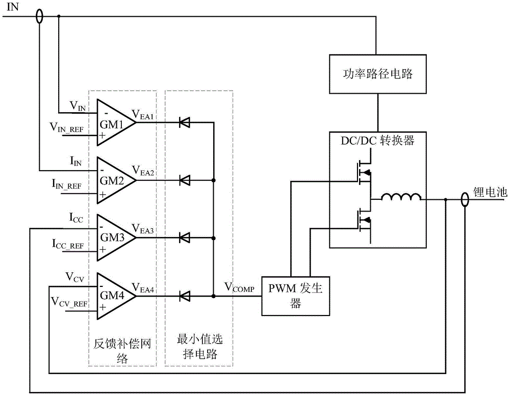
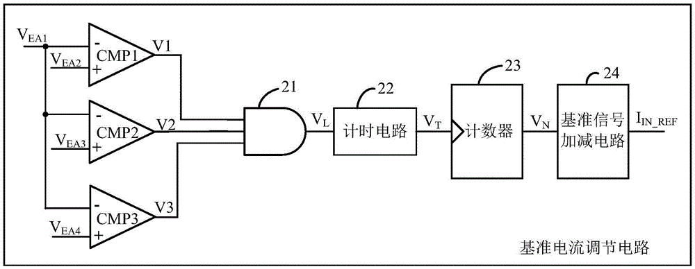
[0053] The control circuit of the switching charger in the embodiment of the present invention includes such as figure 1 The feedback compensation network shown and as figure 2 shown in the reference current regulation circuit, as figure 1 As shown, the switching charger receives an external input power IN and converts it into an appro...


PUM


Abstract

The invention discloses an adaptive charging control circuit and control method for a switch charger. When a reference current adjusting circuit determines that an over-current phenomenon occurs at an input current of a switch charger, an input current reference signal is reduced step by step, thereby reducing the input current of the switch charger; and thus the output voltage of the input power supply returns to a safety value range. Because with a step-by-step input current reduction method, minimization of the charging current of the switch charger can be avoided and a large value can be kept, so that rapid charging can be realized.

Description

technical field [0001] The invention relates to the field of switching power supplies, and more specifically relates to an adaptive charging control circuit and control method used in switching chargers. Background technique [0002] Switching chargers can quickly charge lithium batteries, and are widely used in smart phones, tablet computers and other fields. With the increasing capacity of lithium batteries, charging time is a problem that needs special attention. The current switch charging The charger usually reduces the charging time by increasing the charging current, but in many cases, the charging power is limited by the input power source. Therefore, in order to reduce the charging time, the switching battery charger needs to maximize the use of the energy of the input power source, but at the same time In order not to cause the input power supply to be damaged due to overload, the methods commonly used in the prior art are: [0003] The first is to detect the type...

Claims


Application Information

Patent Timeline
IPC IPC(8): H02J7/00
CPCH02J2207/20H02J7/0071H02J7/00712H02J7/00H02J7/0068
Inventor 邓甫华
Owner NANJING SILERGY SEMICON TECH CO LTD
Why Eureka
Try Eureka