
Subcarrier optical phase-locked loop system

A sub-carrier and optical lock technology, which is applied in the field of sub-carrier optical phase-locked loop system, can solve the problems of narrow operating frequency band of loop filter, performance degradation, narrow operating frequency band of optical phase-locked loop system, etc.

Active Publication Date: 2016-04-06
BEIJING UNIV OF POSTS & TELECOMM
View PDF4 Cites 5 Cited by
  • Summary
  • Abstract
  • Description
  • Claims
  • Application Information

AI Technical Summary

Problems solved by technology

[0004] However, in the prior art, only when the frequency difference between signal light and local oscillator light (U d When the frequency of (t)) is less than the preset frequency, the loop filter can work normally. For the commonly used first-order active filter, it is assumed that the damping coefficient of the filter is ζ, and the natural frequency is f n , only when U d The frequency of (t) is less than 2×ζ×f n , the loop filter can work normally; since the damping coefficient ζ of the filter is a fixed value, the phase error of the optical phase-locked loop system and the natural frequency f n proportional to, if the natural frequency f n When the value is too high, the phase error of the optical phase-locked loop system will increase and the performance will decrease. Therefore, it is necessary to change the natural frequency f n Set within a certain range, which in turn makes the operating frequency band of the loop filter narrower, resulting in a narrower operating frequency band of the optical phase-locked loop system

Method used


Image

  • Subcarrier optical phase-locked loop system
  • Subcarrier optical phase-locked loop system
  • Subcarrier optical phase-locked loop system

Examples


Embodiment Construction

[0017] In order to make the purpose, technical solutions and advantages of the embodiments of the present invention clearer, the technical solutions in the embodiments of the present invention will be clearly and completely described below in conjunction with the drawings in the embodiments of the present invention. Obviously, the described embodiments It is a part of embodiments of the present invention, but not all embodiments. Based on the embodiments of the present invention, all other embodiments obtained by persons of ordinary skill in the art without making creative efforts belong to the protection scope of the present invention.

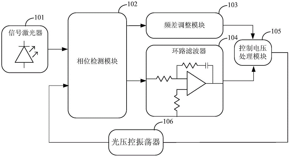
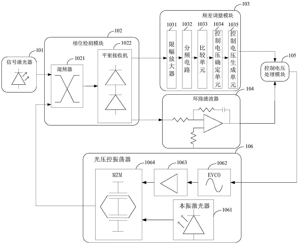
[0018] figure 1 Schematic structure of the subcarrier optical phase-locked loop system provided by the present invention Figure 1 ,Please refer to figure 1 , the subcarrier optical phase-locked loop system includes: a signal laser 101, a phase detection module 102, a frequency difference adjustment module 103, a loop filter 104, a control ...


PUM


Abstract

The embodiments of the invention provide a subcarrier optical phase-locked loop system, comprising a signal laser, a phase detection module, a frequency difference adjusting module, a loop filter, a control voltage processing module and a light pressure controlled oscillator, wherein the phase detection module is used for determining a phase difference signal of signal light and first local oscillator light, and separately sending the phase difference signal to the frequency difference adjusting module and the loop filter; the frequency difference adjusting module is used for determining a first control voltage according to the frequency of the phase difference signal; the loop filter is used for determining a second control voltage according to the frequency of the phase difference signal when the frequency of the phase difference signal is smaller than a preset frequency; and the control voltage processing module is used for determining a comprehensive control voltage according to the first control voltage and the second control voltage, so that the light pressure controlled oscillator generates second local oscillator light according to the comprehensive control voltage and sends the second local oscillator light to the phase detection module. The working band of the subcarrier optical phase-locked loop system is improved.

Description

technical field [0001] Embodiments of the present invention relate to the technical field of optical phase-locked loops, in particular to a subcarrier optical phase-locked loop system. Background technique [0002] With the development of free-space optical communication technology, in order to increase the sensitivity of the free-space optical communication system, an optical phase-locked loop system is used in the free-space optical communication system, through which the frequency of signal light and local oscillator light can be combined and phase lock. [0003] In the prior art, the working principle of the optical phase-locked loop system is as follows: the signal light generated by the signal laser and the local oscillator light generated by the optical voltage-controlled oscillator are transmitted to the phase detection module, and the phase detection module detects the signal light and the local oscillator light Perform processing to obtain the phase difference sig...

Claims


Application Information

Patent Timeline
IPC IPC(8): H03L7/08H04B10/548
CPCH03L7/08H04B10/548
Inventor 张阳安袁学光张锦南丁丁王立猛
Owner BEIJING UNIV OF POSTS & TELECOMM
Learn More