Image forming intelligent high-definition video monitoring system based on optical and electrical correction

A high-definition video and electrical correction technology, applied in the field of intelligent high-definition video surveillance system, can solve the problems of difficult video signal control, unsuitable management of video storage information, image defects, etc., to facilitate the extraction of high-definition video, save daily operating costs, The effect of reducing image defects

Active Publication Date: 2016-04-06
上海亿镜智能科技有限公司
View PDF5 Cites 3 Cited by
  • Summary
  • Abstract
  • Description
  • Claims
  • Application Information

AI Technical Summary

Problems solved by technology

Before the early 1990s, the analog video monitoring system was widely used. However, one video cable in this system can only transmit one analog video signal. Control each video signal as a whole
[0003] Traditionally, in a high-definition video surveillance system, there is a tandem system image forming device, which can simultaneously form original images corresponding to C, M, Y, and K colors respectively. The tandem system image forming device has a plurality of photoreceptors, based on Based on the image data signal decomposed for each color, the photoreceptor corresponding to each color is exposed with a laser beam emitted from an exposure device, and then the photoreceptor is developed to form an original image of each color. Overlaid on the same transfer medium, the image forming device finally forms a color image, and here, an exemplary structure of a scanning exposure apparatus emitting a laser beam for scanning and exposing a photoreceptor in a tandem system image forming device will be described, However, there is a problem that even if optical control is performed using such a mechanism, the scanning line is tilted due to an error or the like, and a tilted image is output
[0004] In contrast, in the prior art, a method is also adopted in which, in the case of monochrome, by adjusting the timing of starting to read data from the line buffer according to the position shift (θ), to improve the image distortion caused by the inclination (θ) of the scanning line, however, there is a problem that such a function of correcting the output position of the scanning line needs to be performed for adjusting the optical path of the laser beam to the lens and each photoreceptor, etc. Therefore, in recent years, studies have been carried out to achieve correct printing by electrically correcting the output position of the scan line without optically correcting it.
[0005] It can be seen from the above that how to better solve the current situation that the video storage information in the existing network video surveillance system is not suitable for management and the limited network transmission bandwidth cannot be fully utilized is still an urgent problem to be solved at present.
The monitoring equipment currently used needs to be equipped with professional terminal equipment to receive and filter the monitoring front-end situation, and the video monitoring system in the prior art has a low degree of intelligence, often cannot obtain satisfactory images, and may even The image defects captured by the current electronic monitoring system are mainly manifested as: blurred images, too dark images, and too bright images. In order to make up for these defects, it is urgent to solve the image problems such as image stripes or uneven density. defect problem

Method used


Image

  • Image forming intelligent high-definition video monitoring system based on optical and electrical correction
  • Image forming intelligent high-definition video monitoring system based on optical and electrical correction
  • Image forming intelligent high-definition video monitoring system based on optical and electrical correction

Examples


Embodiment Construction

[0026] In order to make the technical solutions of the present invention clearer and clearer to those skilled in the art, the present invention will be further described in detail below in conjunction with the examples and accompanying drawings, but the embodiments of the present invention are not limited thereto.

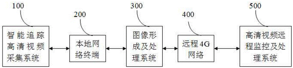
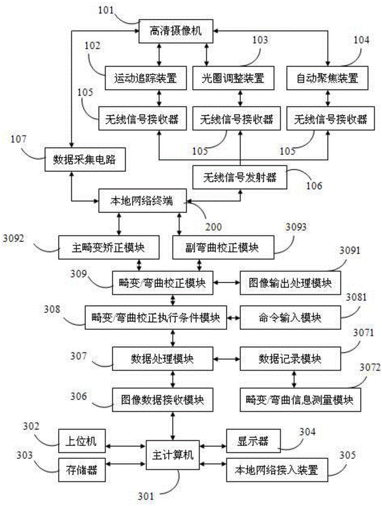
[0027] like figure 1 and figure 2 As shown, an image forming intelligent high-definition video surveillance system based on optical and electrical corrections includes an intelligent tracking high-definition video acquisition system 100, an image forming and processing system 300, and a high-definition video remote monitoring and processing system 500. The intelligent tracking high-definition video The video acquisition system 100 is used to automatically track high-definition video signals and data, the image forming and processing system 300 is used to process the high-definition video signals and data automatically tracked by the intelligent tracking high-definit...


PUM


Abstract

The invention discloses an image forming intelligent high-definition video monitoring system based on optical and electrical correction, and belonging to the technical field of image formation. The system comprises an intelligent tracing high-definition video acquiring system, an image forming and processing system and a high-definition video remote monitoring and processing system; the image forming and processing system comprises a main computer, an image data receiving module, a data processing module, a distortion/bending correction execution condition module, a distortion/bending correction module, a data recording module, a distortion/bending information measurement module, a command input module and an image output processing module; the intelligent tracing high-definition acquiring system comprises a high-definition camera, a data acquiring circuit and a wireless signal emitter; the high-definition remote monitoring and processing system comprises a remote monitoring processing system, a remote video storing system and a remote decoder. The system disclosed by the invention is capable of automatically recognizing and tracing a moving object, automatically adjusting aperture, automatically focusing and reducing the image defect so as to form a high-quality image.

Description

technical field [0001] The invention relates to an intelligent high-definition video monitoring system, in particular to an image forming intelligent high-definition video monitoring system based on optical and electrical correction, and belongs to the technical field of image formation. Background technique [0002] Video surveillance system has been widely used in public security system, telecommunication room, urban transportation, water conservancy system, community security and other fields because of its intuition, convenience and rich information content, and has become an indispensable part of people's real life. So far, video surveillance has mainly experienced three stages of development: analog video surveillance, digital video surveillance and network video surveillance. Before the early 1990s, the analog video monitoring system was widely used. However, one video cable in this system can only transmit one analog video signal. Control each video signal as a whol...

Claims


Application Information

Patent Timeline
Patent Type & Authority Applications(China)
IPC IPC(8): H04N7/18
CPCH04N7/18
Inventor 蒋继平孙飞
Owner 上海亿镜智能科技有限公司
Why Eureka
Try Eureka