Method for attaching optical film sheet to optical display unit

A technology of optical film and optical display, applied in the direction of optical components, optics, nonlinear optics, etc.

Active Publication Date: 2018-06-12
NITTO DENKO CORP
View PDF17 Cites 0 Cited by
  • Summary
  • Abstract
  • Description
  • Claims
  • Application Information

AI Technical Summary

Problems solved by technology

[0005] This Patent Document 2 discloses a method of manufacturing a rectangular film-shaped optical display unit having an electrical terminal for electrical connection formed on one side. optical film, there is no teaching

Method used


Image

  • Method for attaching optical film sheet to optical display unit
  • Method for attaching optical film sheet to optical display unit
  • Method for attaching optical film sheet to optical display unit

Examples


Embodiment Construction

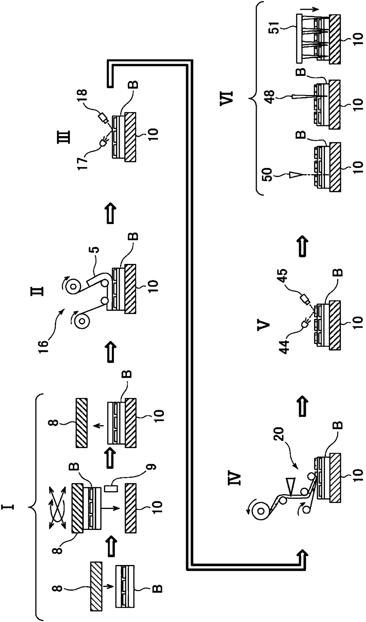
[0074] figure 1 It is a schematic diagram which shows the whole structure of an optical film bonding system in one Embodiment which implements the optical film bonding method of this invention. The optical film bonding system of the present embodiment includes, in order, a position adjustment stage I, a surface protective film peeling stage II, a first surface inspection stage III, a polarized laminate bonding stage IV, a second surface inspection stage V, and a cutting stage VI. As will be described later, the optical display unit 1 moves along the guide rails, and is sequentially transported from the station I to the station VI by a guide mechanism having a self-propelled function.

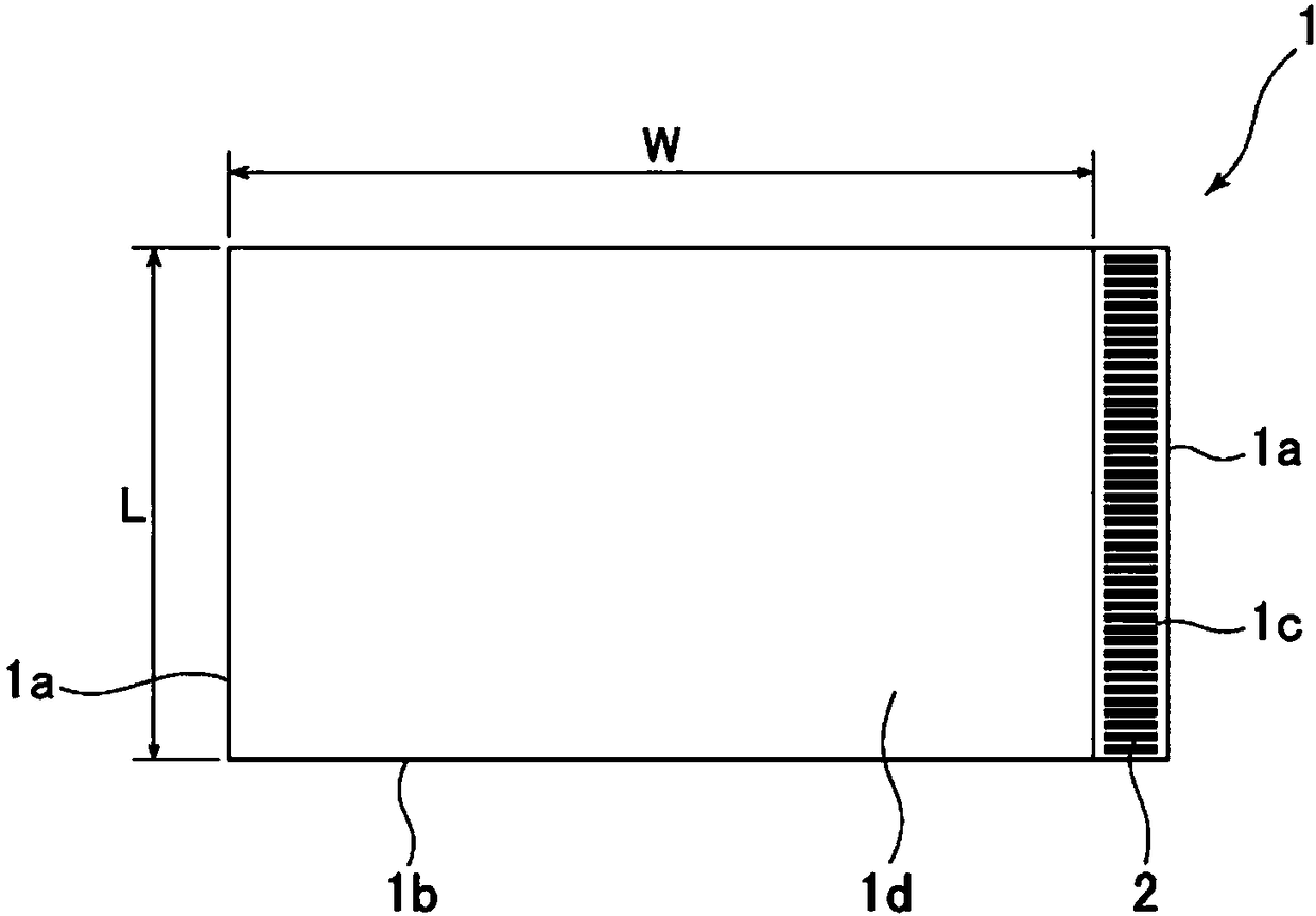
[0075] figure 2 An example of the optical display unit 1 that can be used in one embodiment of the present invention is shown. The planar shape of this optical display unit 1 is a rectangle having a short side 1a and a long side 1b, and a terminal portion 1c having a predetermined width is f...


PUM


Abstract

The method of the present invention uses: a unit assembly motherboard (B), which vertically arranges a plurality of optical display units on a base material in a state in which the side with a terminal portion is located in a transverse direction; an optical film laminate roll (22), It is wound with an optical film laminate on which a carrier film (21e) is bonded via an adhesive layer, the optical film having a width corresponding to the lateral width of the optical display unit except for the terminal portion. width. The method includes the steps of: conveying the unit assembly motherboard to the bonding position; feeding the optical film laminate from a roll to the bonding position; , the optical film and the adhesive layer of the released optical film laminate are sequentially formed with cuts in the transverse direction to form a plurality of optical film sheets supported on the carrier film; The optical film sheet was peeled off from the carrier film while remaining on the optical film side, and bonded sequentially to the optical display surface of each optical display unit on the unit assembly motherboard except for the terminal portion.

Description

technical field [0001] The present invention relates to a method of bonding an optical film sheet to an optical display unit such as an organic EL display unit or a liquid crystal display unit. In particular, the present invention relates to a method of sequentially bonding an optical film sheet to a plurality of rectangular optical display units having terminal portions having electrical terminals for electrical connection formed on one side. Background technique [0002] An optical film comprising a polarizer formed in a long continuous strip with a predetermined width is cut at a predetermined length while being unwound from a roll of the optical film, and the cut sheets of the optical film are sequentially bonded to the It is conveyed to the liquid crystal display unit of a bonding position, and the bonding system and its method of a Roll-To-Panel (RTP) system are comprised by this, for example, it is disclosed by international publication WO2009 / 128241A1 (patent documen...

Claims


Application Information

Patent Timeline
Patent Type & Authority Patents(China)
IPC IPC(8): G09F9/00G02F1/13G02F1/1335
CPCG02F1/13G02F1/1335G09F9/00G02B1/18G02B5/30G09F9/30
Inventor 中西多公岁村上奈穗武田健太郎徐创矢小塩智
Owner NITTO DENKO CORP
Why Eureka
Try Eureka