Pneumoperitoneum no-injury aspirator head end device for laparoscope

A suction head, non-invasive technology, applied in suction devices, wound drainage devices, infusion sets, etc., can solve the problems of delayed observation time point and operation timing, disappearance of observation and operation space, long operation time, etc. High practical value, smooth operation process, and the effect of reducing the number of

Active Publication Date: 2016-04-13
GENERAL HOSPITAL OF PLA
View PDF10 Cites 2 Cited by
  • Summary
  • Abstract
  • Description
  • Claims
  • Application Information

AI Technical Summary

Problems solved by technology

At present, in laparoscopic surgery, the main methods for clearing wound bleeding and exudate are aspirator suction and gauze dipping. The gas is sucked away together, resulting in the collapse of the abdominal wall, and the rapid disappearance of the observation and operation space. It is necessary to wait for continuous inflation to establish a pneumoperitoneum space before continuing to observe and operate, which will delay the best observation time point and surgical operation timing; The gauze is generally a small square gauze, and the small square gauze is only suitable for bleeding and exudate, and the surgical instrument needs to be replaced repeatedly during use, which will delay the operation time
At present, there is no relevant device or product at home and abroad to meet this clinical demand. There is an urgent need for a special medical surgical instrument that can be applied to suck bleeding and exudate in laparoscopic surgery without destroying the pneumoperitoneum pressure and observation space. and applicable to the actual clinical situation

Method used


Image

  • Pneumoperitoneum no-injury aspirator head end device for laparoscope
  • Pneumoperitoneum no-injury aspirator head end device for laparoscope
  • Pneumoperitoneum no-injury aspirator head end device for laparoscope

Examples


Embodiment Construction

[0022] The present invention will be further described in detail below in conjunction with the accompanying drawings and embodiments.

[0023] The following examples are only examples for clearly illustrating the present invention, rather than limiting the implementation of the present invention. For those of ordinary skill in the art, on the basis of the following descriptions, other different forms of changes or changes can also be made, and these obvious changes or changes that belong to the spirit of the present invention are still within the protection scope of the present invention middle.

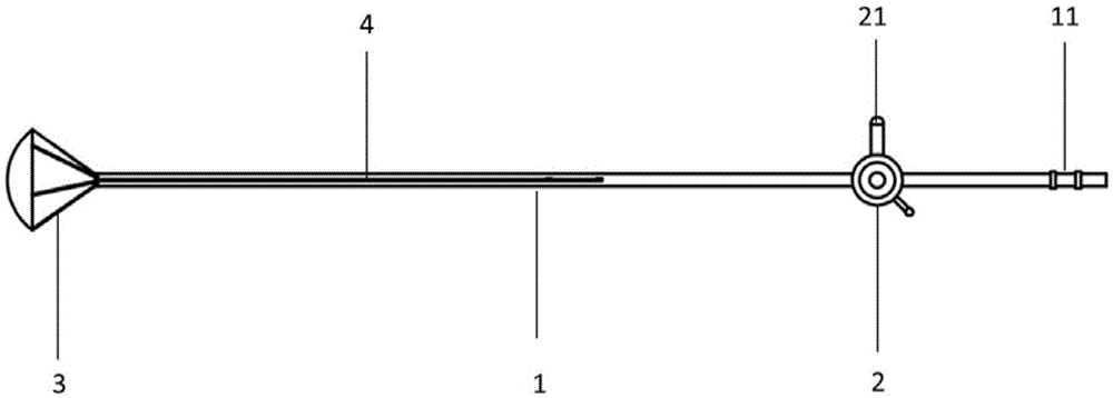
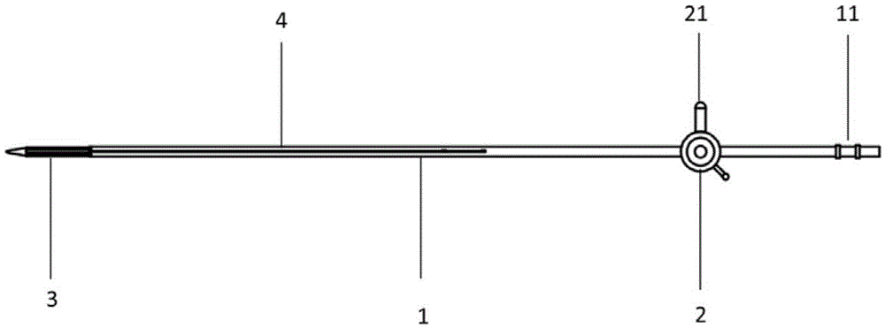
[0024] Such as figure 1 , figure 2 As shown, the pneumoperitoneum non-invasive aspirator head-end device proposed by the present invention includes the following parts: suction tube (1), control valve (2), dipping and sucking sponge ball (3) and sponge ball controller ( 4). The four parts form a unified whole when used to implement the attraction function, such as figure 1 , ...


PUM


Abstract

The invention discloses a pneumoperitoneum no-injury aspirator head end device for a laparoscope. The head end device comprises a suction tube, a control valve, a dipping sponge ball and a sponge ball controller. The suction tube is of a middle bracket structure with the back end communicated with the inner cavity of the control valve; the headmost end of the suction tube and the dipping sponge ball are connected, and the headmost end of the suction tube and the dipping sponge ball are screwed by screw threads and are in sealed connection. The dipping sponge ball comprises outer side conical brackets, a connecting webbing membrane between the conical brackets, elastic sponges in the conical brackets and an arc-shaped top constituted by a front-end unidirectional water-permeable composite fiber membrane, so that the unidirectional circulation of sucked peritoneal fluid is guaranteed, the backflow of dipped liquid is prevented and the possibility that a pneumoperitoneum is injured is reduced. The sponge ball controller, which sleeves outside the dipping sponge ball, can be used for controlling the opening/closing of the dipping sponge ball and facilitating the placement or the withdrawal of the pneumoperitoneum no-injury aspirator head end device for the laparoscope from an abdominal puncture hole. The device disclosed by the invention is relatively suitable for gas laparoscopic operations.

Description

technical field [0001] The invention relates to the technical field of instruments for minimally invasive surgery, in particular to a head end device of a pneumoperitoneum non-invasive aspirator for laparoscopy. Background technique [0002] Laparoscopic surgery is a minimally invasive surgical technique. Due to the advantages of small intraoperative trauma and fast postoperative recovery, it has rapidly emerged in recent years. Laparoscopic surgery has been widely used in general surgery, obstetrics and gynecology, urology, bone and joint surgery Surgery, Thyroid and Breast Surgery, etc. During laparoscopic surgery, a good surgical field of view and operating space are the key to ensure the smooth progress of the operation, and effective insufflation pressure (maintain the insufflation pressure at 12mmHg-16mmHg through CO2 insufflation machine) and clean (no bleeding) ) surgical wound is an important guarantee for laparoscopic surgery. At present, in laparoscopic surgery,...

Claims


Application Information

Patent Timeline
Patent Type & Authority Applications(China)
IPC IPC(8): A61M1/00A61M27/00A61M3/02A61B17/00
CPCA61M1/0023A61B17/00234A61M3/0279A61M27/00A61M1/743
Inventor 卫勃崔建新郗洪庆陈志达刘国晓周思欣陈凛
Owner GENERAL HOSPITAL OF PLA
Why Eureka
Try Eureka