Agitator tank

A technology of a stirring tank and a stirring motor, which is applied to the accessories of a mixer, a mixer with a rotating stirring device, and dissolution, etc., can solve the problems of small external vibration transmission, poor vibration isolation effect, and easy bending and damage of motor wires, so as to avoid Effects of wire damage

Inactive Publication Date: 2016-04-13
JIANGSHAN XIANJIN ELECTRICAL & MECHANICAL TECH SERVICES CO LTD
View PDF5 Cites 10 Cited by
  • Summary
  • Abstract
  • Description
  • Claims
  • Application Information

AI Technical Summary

Problems solved by technology

[0003] The invention provides a stirring tank with adjustable direction of lead wire inlet and outlet and small amount of external vibration transmission, which solves the problems of poor vibration isolation effect of existing stirring tanks and easy bending and damage of motor wires

Method used


Image

  • Agitator tank
  • Agitator tank
  • Agitator tank

Examples


Embodiment 1

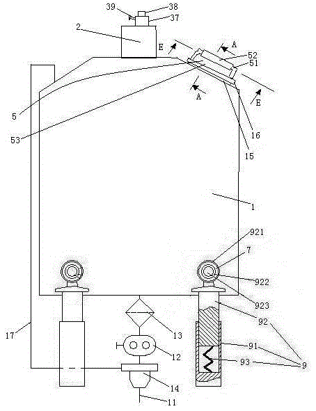
[0027] Embodiment one, see figure 1 , a stirring tank, comprising a stirring tank body 1 and a stirring motor 2. The stirring tank body 1 is provided with a discharge pipe 11 . The discharge pipe 11 is provided with a slurry metering pump 12 . The inlet end of the slurry metering pump 12 is provided with a slurry filter 13 . The outlet end of the slurry metering pump 12 is provided with a two-position three-way valve 14 . One outlet of the two-position three-way valve 14 communicates with the stirring tank body 1 through the return pipe 17 , that is, the excess slurry is returned to the stirring tank body 1 .

[0028]The stirring tank body 1 is provided with supporting feet 9 . The supporting foot 9 includes a lower section 91 and an upper section 92 . The upper end of the lower section 91 is slidably sleeved on the lower end of the upper section 92 . The lower section 81 is provided with a damping spring 93 supporting the upper section 92 . The upper end of the upper s...

Embodiment 2

[0042] Embodiment two, the difference with embodiment one is:

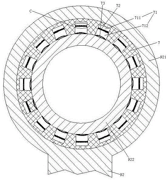
[0043] see Figure 9 , The supporting foot 9 is also provided with a driving mechanism 6 . The inner ring 922 is rotatably connected to the rubber ring 7 , and the rubber ring 7 is fixedly connected with the connecting ring 921 .

[0044] The drive mechanism 6 includes a ratchet 61 , a pawl 62 for driving the ratchet, and a drive rod 63 . The ratchet 61 is coaxially connected with the inner ring 922 . The ratchet 61 is integrated with the inner ring 922 . The pawl 62 is fixedly connected to one end of the driving rod 63 . The upper section 92 is provided with a sliding hole 924 . The other end of the driving rod 63 can slide through the sliding hole 924 two-dimensionally. The lower end of the drive rod 63 is slidably hooked to the lower section 91 along the radial direction of the connecting ring 921 (see figure 1 ) are fixed together. The driving rod 63 is provided with a storage hole 64 . There are two ...


PUM


Abstract

The invention relates to an agitator tank. The agitator tank comprises an agitator tank body and an agitator motor. The agitator tank body is provided with support legs. The support leg comprises an upper section and a lower section. A damper spring for supporting the upper section is arranged in the lower section. The upper section is provided with a connection ring. An inner ring goes through the connection ring. The inner ring is connected to the connection ring through a rubber ring. A connection pin goes through the inner ring. The upper section is connected to the agitator tank body through the connection pin. A lead inlet/outlet and a tube head are arranged at a compressor. The tube head is provided with a spherical head. A spherical cavity is arranged at the lead inlet/outlet. The tube head is clamped in the spherical cavity through the spherical head and is hinged to the lead inlet/outlet. The tube head is fixedly connected to the lead inlet/outlet through a puller bolt. The agitator tank realizes adjustment of a lead inlet/outlet direction and a less vibration transmitting amount and solves the problem that the existing agitator tank has poor vibration isolation effects.

Description

technical field [0001] The invention relates to a stirring container, in particular to a stirring tank. Background technique [0002] The stirring tank includes a stirring tank body and a stirring motor. The existing mixing tank has the following disadvantages: vibration will be generated during the mixing process, and the external transmission of vibration will interfere with peripheral equipment and affect the color matching effect; the import direction of the wire inlet and outlet of the stirring motor cannot be adjusted, and the wire will be bent due to transitional bending. phenomenon of damage. Contents of the invention [0003] The invention provides a stirring tank with adjustable direction of the lead wire inlet and outlet and small amount of external vibration transmission, which solves the problems of poor vibration isolation effect and easy bending damage of the motor lead in the existing stirring tank. [0004] The above technical problems are solved by the ...

Claims


Application Information

Patent Timeline
Patent Type & Authority Applications(China)
IPC IPC(8): B01F7/00B01F15/00
CPCB01F27/00B01F35/00
Inventor 危金兰
Owner JIANGSHAN XIANJIN ELECTRICAL & MECHANICAL TECH SERVICES CO LTD
Why Eureka
Try Eureka