Roller type dust removing device

A dust removal device and a drum-type technology, which are applied in cleaning flexible objects, cleaning methods and utensils, cleaning methods using tools, etc., can solve problems such as no increase in production efficiency, unstable air pump pressure, and decreased production efficiency, so as to reduce errors. The effect of reducing the risk of judgment, reducing running time, and improving production efficiency

Active Publication Date: 2016-04-13
WUHAN JINGCE ELECTRONICS GRP CO LTD
View PDF8 Cites 1 Cited by
  • Summary
  • Abstract
  • Description
  • Claims
  • Application Information

AI Technical Summary

Problems solved by technology

However, due to differences in clean room standards, unstable air pump pressure, dust, lint, dirt, etc. on the surface of the LCD module, even though the particles are cleaned by air blowing, they still cannot be effectively cleaned and still exist. If the software runs for too long, the risk of misjudgment cannot be reduced. It is necessary to increase manual inspection and re-inspection after the inspection, which leads to a decrease in production efficiency.
[0003] In the existing production, in order to better clean the surface of the liquid crystal module, a cleaning manpower is added to the production line, that is, the surface of the liquid crystal module is manually cleaned with rollers before the air blowing cleaning. In this way, although the surface of the liquid crystal module The problem of surface cleaning has been improved, but a new problem has arisen: the increase in manpower corresponds to the increase in cost. Due to the use of manual cleaning, the LCD module needs to stay on the assembly line, so that the production efficiency not only does not increase but decreases
[0004] Particles attached to the surface of the liquid crystal module, the existing air pump drives the ion air knife to clean the surface of the particles by blowing air, which cannot fundamentally solve the problem of misjudgment caused by the attachment of particles, and the increase in manual cleaning has led to production drop in efficiency

Method used


Image

  • Roller type dust removing device
  • Roller type dust removing device

Examples


Embodiment Construction

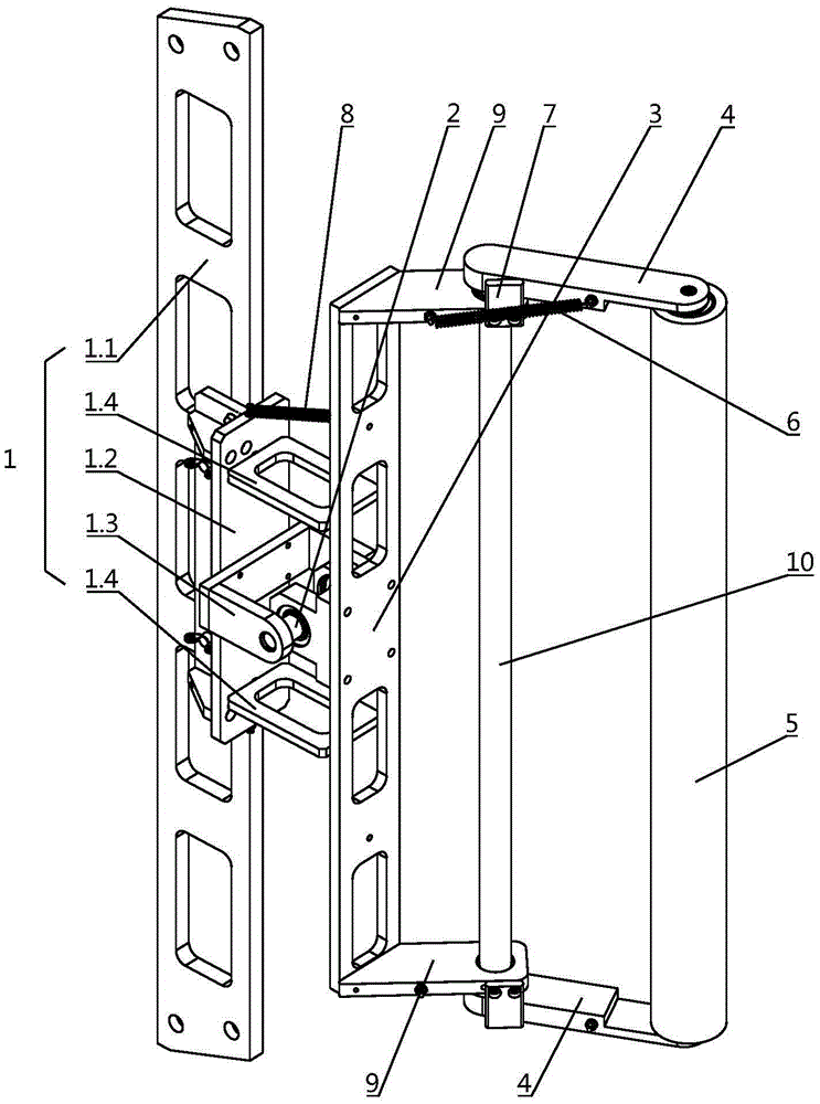
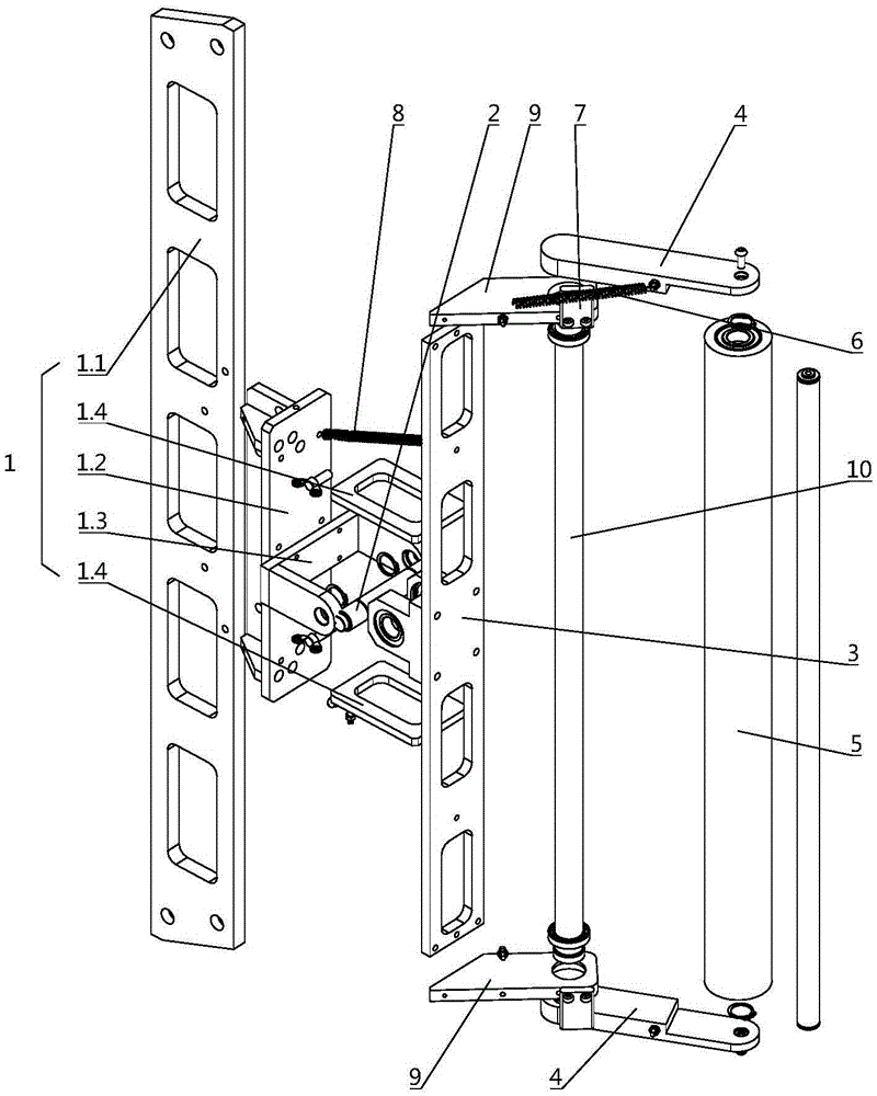
[0018] pass below Figure 1 ~ Figure 2 And the way of enumerating some optional embodiments of the present invention, the technical solution of the present invention (including the preferred technical solution) is described in further detail, and any technical feature and any technical solution in this embodiment do not limit the protection scope of the present invention .

[0019] Such as figure 1 with figure 2 The drum-type dust removal device shown includes a mounting frame 1, and the mounting frame 1 is rotatably connected to the middle part of a mounting plate 3 through a horizontal rotating shaft 2. The length direction of the mounting plate 3 is perpendicular to the horizontal rotating shaft 2, and the mounting plate 3 The two ends of the length direction are all rotatably connected to a roller mounting seat 4, and one end of the roller mounting seat 4 is connected to the end of the mounting plate 3 and rotates on an axis parallel to the length direction of the mount...


PUM


Abstract

The invention discloses a roller type dust removing device. The roller type dust removing device comprises an installing frame. The installing frame is rotationally connected with the middle of an installing plate through a horizontal rotating shaft, the length direction of the installing plate is perpendicular to the horizontal rotating shaft, the two ends of the installing plate in the length direction are each rotationally connected with a roller installing base, one ends of the roller installing bases are connected with the ends of the installing plate and rotate in the direction parallel to the length direction of the installing plate as the axis, a rotary roller is arranged between the other ends of the roller installing bases located at the two ends of the installing plate, and sticky coatings are arranged on the surfaces of the rollers. The roller type dust removing device has the beneficial effects that fine particles on the surfaces of liquid crystal modules are automatically removed through the horizontal rotating shaft and the rollers with the rotating radius, self-adaptation adjustment can be carried out on the liquid crystal modules at different positions and different inclination angles, the purposes of the high cleaning speed, high efficiency and high cleanliness are achieved, the running time of a software background is shortened, and the misjudgment risk of detection equipment is reduced. The device can achieve self-adaptation adjustment, manual intervention is not needed, and production efficiency is greatly improved.

Description

technical field [0001] The invention relates to the field of API automatic optical equipment detection, in particular to a drum-type dust removal device for cleaning particles on the surface of a liquid crystal module. Background technique [0002] To detect liquid crystal modules in API automatic optical equipment, it is necessary to use industrial cameras to obtain several specific screen images of lit liquid crystal modules and to turn off the pictures of particles with backlight on liquid crystal modules, and then use software to process, analyze and compare the obtained pictures , so as to obtain the real defects and false defects of the liquid crystal module to confirm the qualification of the module; when the surface of the liquid crystal When the surface of the module is covered with particles, the detection software will run in the background for a long time and will misjudge the particles as real defects; therefore, there will be a cleaning action before the API de...

Claims


Application Information

Patent Timeline
Patent Type & Authority Applications(China)
IPC IPC(8): B08B11/00B08B1/04B08B7/00
CPCB08B1/04B08B7/0028B08B11/00
Inventor 洪浩
Owner WUHAN JINGCE ELECTRONICS GRP CO LTD
Why Eureka
Try Eureka