Novel corner crimping machine

A corner-setting machine and corner-setting technology, which is applied in the direction of metal processing equipment, etc., can solve the problems of unstable feeding, failure to meet the requirements of use, and high noise, and achieve the effect of simple structure, meeting the requirements of use, and stable working performance

Inactive Publication Date: 2016-04-13
广东欧亚特机械设备有限公司
View PDF6 Cites 1 Cited by
  • Summary
  • Abstract
  • Description
  • Claims
  • Application Information

AI Technical Summary

Problems solved by technology

[0004] The purpose of the present invention is to provide a new type of angle-setting machine, aiming to solve the problem that the existing angle-setting ma

Method used


Image

  • Novel corner crimping machine

Examples


Example Embodiment

[0019] In order to make the objectives, technical solutions and advantages of the present invention clearer and clearer, the present invention will be further described in detail below with reference to the accompanying drawings and embodiments.

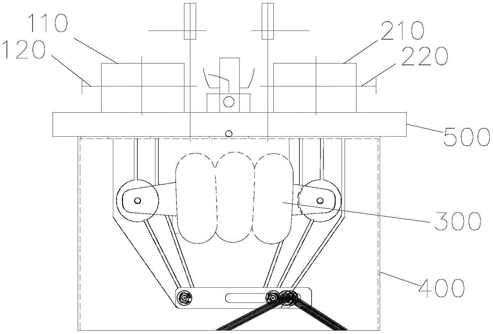
[0020] Such as figure 1 As shown, a new type of corner assembly machine includes:

[0021] The left corner skateboard 110;

[0022] The left punching riveting shaft 120 provided on the left group corner sliding plate 110;

[0023] The left group corner knife set on the left punching riveting shaft 120;

[0024] Right group corner skateboard 210;

[0025] The right punching riveting shaft 220 provided on the right group corner sliding plate 210;

[0026] The right group corner knife set on the right punching riveting shaft 220;

[0027] The left corner slide 110 and the right corner slide 210 are respectively connected with the airbag type power unit 300, and the left corner slide 110 and the right corner slide 210 are driven by the airbag type p...


PUM


Abstract

The invention discloses a novel corner crimping machine comprising a left corner crimping sliding plate, a left piercing-riveting shaft, a left corner crimping tool, a right corner crimping sliding plate, a right piercing-riveting shaft and a right corner crimping tool, wherein the left piercing-riveting shaft is arranged on the left corner crimping sliding plate; the left corner crimping tool is arranged on the left piercing-riveting shaft; the right piercing-riveting shaft is arranged on the right corner crimping sliding plate; the right corner crimping tool is arranged on the right piercing-riveting shaft; and the left corner crimping sliding plate and the right corner crimping sliding plate are respectively connected with an air-sac-type power unit by which the left corner crimping sliding plate is driven to be close to or separated from the right corner crimping sliding plate. According to the novel corner crimping machine, the air-sac-type power unit is arranged to drive the corner crimping tools to realize 90-DEG connection of aluminum doors and windows; the air-sac-type power unit has the various advantages of zero friction during working, no maintenance need and stable working performance; the actions of the corner crimping tools are driven by the air-sac-type power unit instead of an oil cylinder/an air cylinder, so that the stability of each corner crimping tool in working and the workpiece machining quality are ensured.

Description

technical field [0001] The invention relates to a novel corner forming machine. Background technique [0002] The angle forming machine is a special equipment for the production of high-grade broken bridge aluminum alloy doors and windows. The angle forming oil cylinder / air cylinder pushes the angle forming slide plate, the forming angle slide plate moves forward, and at the same time pushes the left and right punching shafts, and the angle setting knife on the punching shaft achieves alignment. Aluminum doors and windows are connected at a 90-degree angle. However, when the existing angle group oil cylinder / air cylinder is working, the feed is unstable and the noise is large, which cannot meet the requirements for use. [0003] Therefore, the prior art still needs to be improved and developed. Contents of the invention [0004] The purpose of the present invention is to provide a new type of corner-setting machine, aiming to solve the problem that the existing corner-se...

Claims


Application Information

Patent Timeline
IPC IPC(8): B21D39/00B21D53/74
CPCB21D39/00B21D53/74
Inventor 罗贵兴
Owner 广东欧亚特机械设备有限公司
Why Eureka
Try Eureka