Automatic container cutting device

A cutting device and container technology, applied in shearing devices, accessories of shearing machines, tools for shearing machines, etc., can solve the problem of low degree of automation, incomplete cutting, inability to use vacuum environment or fully automated platform, etc. problems, to achieve the effect of high degree of automation, saving manpower, eliminating overload torque and incomplete cutting or poor cutting accuracy

Inactive Publication Date: 2016-04-13
HANGZHOU JINGYE INTELLIGENT TECH CO LTD
View PDF7 Cites 3 Cited by
  • Summary
  • Abstract
  • Description
  • Claims
  • Application Information

AI Technical Summary

Problems solved by technology

[0005] In order to overcome the defects that the traditional mechanical cutting device has a low degree of automation, cannot be applied in a vacuum environment or a fully automated platform, and the cutting is not complete, the technical problem to be solved by the present invention is: to provide a fully automatic operation of the entire cutting process, which is safe and reliable. , Cutting precise automatic container cutting device

Method used


Image

  • Automatic container cutting device
  • Automatic container cutting device
  • Automatic container cutting device

Examples


Embodiment 1

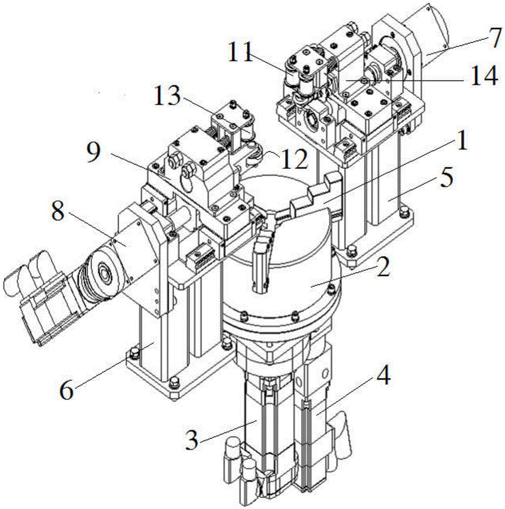
[0037] Embodiment 1: as figure 1 , figure 2 As shown, an automatic container cutting device includes a three-jaw chuck for placing tank containers, a cutting unit 14, a controller, a first mounting base 5, and a second mounting base 6,

[0038] The three-jaw chuck includes a jaw 1 and a chuck body 2, the chuck body 2 is driven by a first drive motor 3 to realize rotation and speed change, and the jaw 1 is driven by a second drive motor 4 to realize inward or move outward;

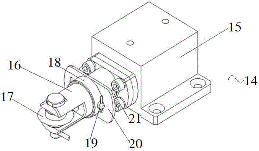
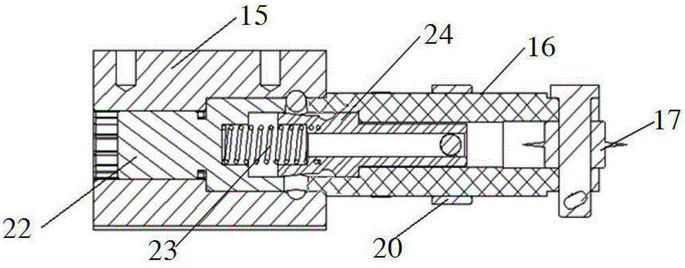
[0039] The cutting unit 14 includes a knife bar mount 15 and a knife bar 16, the knife bar 16 is installed on the knife bar mount 15, and a cutting blade 17 is installed on the knife bar 16;

[0040] The first installation base 5 is provided with a linear guide rail, and the bottom of the knife bar mounting seat 15 is provided with a slider that matches the linear guide rail, and the knife bar mounting seat 15 is driven by the third drive motor The block moves along the linear guide rail;

[0041] The se...

Embodiment 2

[0047] Embodiment 2: as figure 1 , figure 2 As shown, an automatic container cutting device is different from Embodiment 1 in that the container cutting device also includes a clamping assembly, and the clamping assembly includes a first clamping part 11 for contacting with the tank container And the second clamping part 13, the first clamping part 11 is installed on the cutting unit 14, the second clamping part 13 is installed on the clamping mechanism 9, the first clamping part 11 and the second The parts in the clamping part 13 that are used to be in contact with the tank container are rollers, the number of rollers in each clamping part is 2, and the contact elements 12 on the clamping mechanism 9 are rollers. Wherein, the arrangement of each clamping portion and the rollers in the tightening mechanism 9 makes the rotation resistance of the tank container during the rotation process smaller. The arrangement of the first clamping part 11 and the second clamping part 13 c...

Embodiment 3

[0049] Embodiment 3: as Figure 1 to Figure 4 As shown, an automatic container cutting device differs from Embodiment 1 or Embodiment 2 in that the cutting unit 14 also includes a spline shaft 22 and a spring 23, and the spline shaft 22 is connected to the cutter bar 16, The inside of the knife rod 16 is sleeved with a knife rod mandrel 24, and one end of the knife bar mandrel 24 is equipped with a push rod 19, and the said knife rod 16 is provided with a chute 21, and the said push rod 19 extends through the chute 21 to Outside the knife bar 16, the other end of the knife bar mandrel 24 is a steel ball positioning arc-shaped groove 242 and a tapered surface structure 243 that gradually increases in taper. The steel ball positioning arc-shaped groove 242 is provided with several steel balls. The spline shaft 22 is provided with a plurality of steel ball positioning holes, and the spring 23 is in contact with the spline shaft 22 and the knife bar core 24 respectively. When the ...


PUM


Abstract

The invention relates to an automatic container cutting device in which the cutting procedure can automatically run. The cutting device comprises a three jaw chuck, a cutting unit, a controller, a first installing base and a second installing base. The three jaw chuck comprises jaws and a chuck body. The chuck body is driven by a first drive motor to achieve rotating and speed changing. The jaws are driven through a second drive motor to achieve inward or outward movement. The first installing base is provided with a linear guide rail. The cutting unit can be driven by a third drive motor to move along the linear guide rail. The second installing base is provided with an ejecting mechanism corresponding to the cutting unit. The ejecting mechanism is provided with a contact element used for making contact with a tank container. The second installing base is provided with a linear guide rail. The ejecting mechanism can be driven by a fourth drive motor to move along the linear guide rail. The first drive motor, the second drive motor, the third drive motor and the fourth drive motor are all connected with the controller.

Description

technical field [0001] The invention relates to a container cutting device, in particular to a container cutting device with fully automatic cutting process. Background technique [0002] When cutting tank containers, two methods are generally used: manual cutting and mechanical cutting. Wherein, manually cutting the tank container often has defects such as high labor intensity, low cutting efficiency, and harm to the human body. However, the use of mechanical cutting tank containers generally has the problem of low automation and inevitably requires manual participation. Moreover, when it is necessary to cut containers in a fully automated operation platform or in a vacuum environment, the traditional semi-automatic mechanical cutting cannot be applied at all, and a container cutting device with a fully automated operation of the cutting process must be equipped. [0003] In addition, when the tank container that needs to be cut is made of plastic, whether it is manual cu...

Claims


Application Information

Patent Timeline
Patent Type & Authority Applications(China)
IPC IPC(8): B23D31/00B23D33/04B23D35/00
CPCB23D31/003B23D33/04B23D35/00B23D35/004
Inventor 郭湖兵童毅高嵘岗来建良
Owner HANGZHOU JINGYE INTELLIGENT TECH CO LTD
Why Eureka
Try Eureka