Railway vehicle frame and bogie

A rail vehicle and bogie technology, which is applied in the field of railway locomotive vehicle structure design, can solve the problems of not involving the integrated installation of brake units, large space occupied by the bogie area, and high installation position of secondary springs, so as to increase the interior space of the vehicle, Good structural performance, the effect of reducing the overall and local height

Active Publication Date: 2016-04-13
ZHUZHOU ELECTRIC LOCOMOTIVE CO
View PDF5 Cites 12 Cited by
  • Summary
  • Abstract
  • Description
  • Claims
  • Application Information

AI Technical Summary

Problems solved by technology

[0005] Chinese patent application CN201310214128.3 discloses a bogie, which adopts a wheel-side permanent magnet synchronous motor to directly drive a 100% low-floor bogie with independent wheels and wheelsets, but the installation position of the secondary spring of this invention is high, and the bogie area takes up space Large, limited by the height of th

Method used


Image

  • Railway vehicle frame and bogie
  • Railway vehicle frame and bogie
  • Railway vehicle frame and bogie

Examples


Embodiment Construction

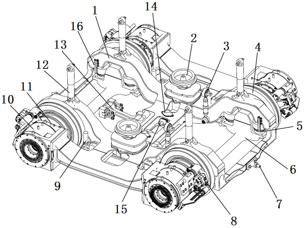
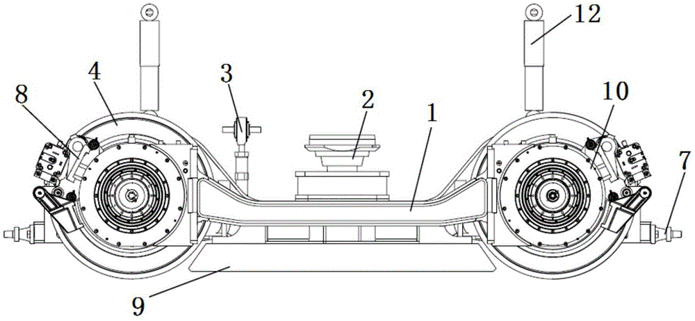
[0031] A rail vehicle bogie driven directly by wheel-side permanent magnet motors, such as Figure 1-4 As shown, the bogie mainly includes frame 1, traction device 13, independent wheels 4, axle bridge 6, primary suspension device 5, secondary suspension device 2, hydraulic braking device 8, magnetic rail brake 9 and other parts.

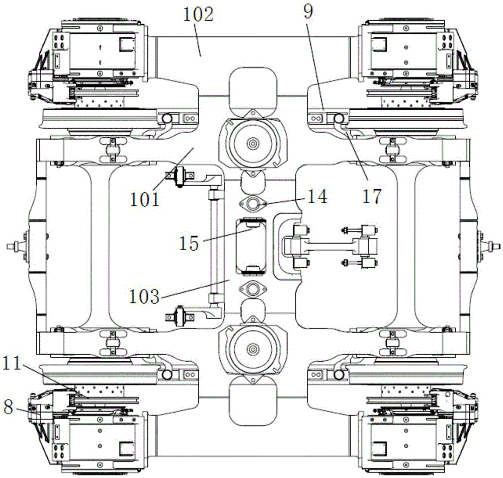
[0032] The bogie adopts a layered box-type welded frame, and its specific structure is that the motor suspension beam 102 of the frame 1 is a cantilever structure, the height of the upper cover plate of the motor suspension beam is higher than that of the crossbeam 103, and the side rails pass between the cover plates. The upper cover plate of the beam 101 is connected to reduce the stress concentration of the frame and improve the stress condition of the frame. The layered structure can meet the space requirements of the magnetic track brake 9 and allow the vertical plate structure of the cantilever structure of the motor suspension beam to have a ...


PUM


Abstract

The invention discloses a railway vehicle frame and a bogie. The railway vehicle frame is a layered box-like frame; the frame is provided with a cantilever type motor suspension beam; the height of an upper cover plate of the motor suspension beam is larger than that of a cross beam upper cover plate of the frame; the upper cover plate of the motor suspension beam is fixedly connected with the cross beam upper cover plate of the frame through an upper cover plate on a frame side beam; a mounting space for a magnetic track brake is formed on the frame; the mounting space for the magnetic track brake is positioned under the motor suspension beam; and a secondary suspension mounting seat is arranged at the middle part of the frame side beam. According to the invention, 100% of low-floor target can be realized, the taking area is large, the strength of the layered frame is great and the railway vehicle frame satisfies lightweight requirements.

Description

technical field [0001] The invention relates to a rail vehicle frame and a bogie, which is mainly used for a 100% low-floor bogie that directly drives an independent wheel set by a wheel permanent magnet motor, and relates to the structural design field of railway locomotives. Background technique [0002] In recent years, with the reduction of the cost of permanent magnet materials and the improvement of performance, permanent magnet synchronous motors have attracted more and more attention from developers of rail traction systems due to their high efficiency and high power density. At the same time, the permanent magnet motor direct drive mode is easy to realize the weight reduction of the bogie because it does not need an additional gear transmission device, and has a good application prospect. [0003] The traditional track traction technology needs to install a gear transmission device between the traction motor and the wheel set, which increases the transmission loss o...

Claims


Application Information

Patent Timeline
IPC IPC(8): B61F5/52
CPCB61F5/52
Inventor 肖梯高祥陈国胜陈喜红谢加辉陶功安易兴利
Owner ZHUZHOU ELECTRIC LOCOMOTIVE CO
Why Eureka
Try Eureka