Disc plucker

The technology of a disc grabbing machine and a cotton hopper is applied in the field of textile machinery, which can solve the problems of low efficiency, easy blockage of the cotton hopper, cumbersome structure, etc., and achieves the effects of convenient operation, simple structure, and easy blockage.

Active Publication Date: 2016-04-13
HUBEI JINAN TEXTILE GRP CO LTD
View PDF11 Cites 11 Cited by
  • Summary
  • Abstract
  • Description
  • Claims
  • Application Information

AI Technical Summary

Problems solved by technology

[0003] The object of the present invention is to provide a simple structure, easy to use, suitable for grabbing cotton bundles and cotton bl...

Method used


Image

  • Disc plucker
  • Disc plucker
  • Disc plucker

Examples


Embodiment Construction

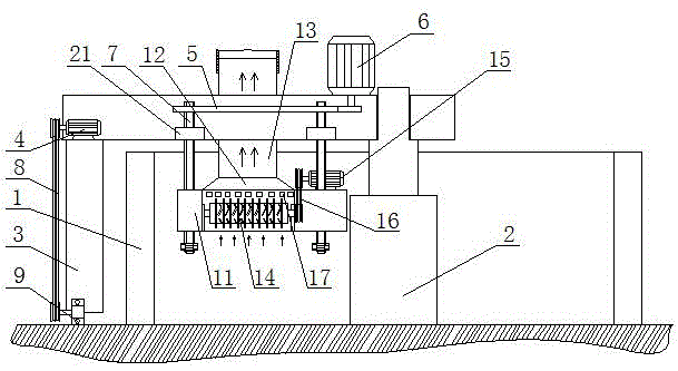
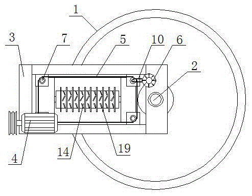
[0016] The disc plucking machine is composed of a silo 1, a central column 2, a drive stand 3, a drive motor 4, a drive wheel 9, a transmission motor 6, a transmission screw 7 and a cotton collection device; the circular silo 1 center The center column 2 is installed in the position; the drive stand 3 with an "L" shape in the cross section is movable on the center column 2; one end of the drive stand 3 extends to the outside of the silo 1; The drive wheel 9 is equipped with at the bottom of the frame 3; the drive wheel 9 is rollingly connected with the ground. Drive motor 4 is housed on the drive stand 3 above drive wheel 9; Drive motor 4 is connected with drive wheel 9 by transmission belt A8.

[0017] The drive stand 3 on one side of the central column 2 is equipped with a drive motor 6, and the drive stand 3 below the drive motor 6 is equipped with a drive screw 7 through a bearing seat 21; the drive motor 6 is connected with the drive screw 7 through a transmission belt B1...


PUM


Abstract

The invention relates to a disc plucker and belongs to the technical field of textile machinery. The disc plucker comprises a stock bin, a center stand column, a drive floorstand, a drive motor, a drive wheel, a transmission motor, a transmission lead screw and a cotton collecting device; the center of the stock bin is provided with the center stand column; the center stand column is movably provided with the drive floorstand; one end of the drive floorstand extends to the outside of the stock bin; the position, extending to the outside of the stock bin, of the bottom of the drive floorstand is provided with the drive wheel through the drive motor and a transmission belt A, the transmission motor is arranged at the position, on one side of the center stand column, of the drive floorstand, the drive floorstand below the transmission motor is provided with the cotton collecting device through the transmission lead screw, and the transmission motor is connected with the transmission lead screw through a transmission belt B. The disc plucker is simple in structure and convenient to operate, the problems that a cotton collecting hopper of an existing plucker is easy to block, the structure is unwieldy, and efficiency is low are solved, and the disc plucker is particularly suitable for production and use of enterprises.

Description

technical field [0001] The invention relates to a disc plucking machine, which belongs to the technical field of textile machinery. Background technique [0002] Cotton yarn used in the textile industry is made from cotton fibers processed through the spinning process. In this process, it is first necessary to use the plucking machine to grab cotton bundles and cotton blocks from the bundled cotton raw materials, and then transport them to the following machinery through negative pressure pipelines for processing and production in the next step. Due to the limitations of the structure, the existing plucking machine often has the problem of cotton bundles and cotton blocks blocking the cotton collection hopper; it cannot meet the needs of enterprise production; in addition, the existing plucking machine still has the problems of heavy structure and low efficiency . Therefore, it is necessary to develop a cotton catching device with simple structure and easy to use to solve ...

Claims


Application Information

Patent Timeline
IPC IPC(8): D01G7/02D01G7/06
CPCD01G7/02D01G7/06
Inventor 胡兴桃
Owner HUBEI JINAN TEXTILE GRP CO LTD
Why Eureka
Try Eureka