Impeller assembly machine

A technology for assembly machines and impellers, which is applied to mechanical equipment, machines/engines, liquid fuel engines, etc., can solve problems such as inability to quickly turn the blade, poor adjustability of the rolling riveting mechanism, and unreasonable design of the rotor structure, and achieve the goal of turning the blade Stable pace, improved work efficiency, and improved efficiency

Inactive Publication Date: 2016-04-13
南通市京山锦纶有限公司
View PDF5 Cites 13 Cited by
  • Summary
  • Abstract
  • Description
  • Claims
  • Application Information

AI Technical Summary

Problems solved by technology

[0005] However, the rotor structure in the above-mentioned patent has the problem of unreasonable design and inability to quickly rotate the rotor, and the adjustability of the rolling riveting mechanism is also very poor. The most important thing is that it is only suitable for assembling impellers with a single-layer structure. Due to the long overall length of the impeller, and the middle part of the impeller also needs to install a reinforced isolation plate that divides the impeller into two chambers, which cannot be realized only by using the above-mentioned patented equipment.

Method used


Image

  • Impeller assembly machine
  • Impeller assembly machine
  • Impeller assembly machine

Examples


Embodiment Construction

[0046] The present invention will be described in further detail below in conjunction with the accompanying drawings.

[0047] This specific embodiment is only an explanation of the present invention, and it is not a limitation of the present invention. Those skilled in the art can make modifications to this embodiment without creative contribution as required after reading this specification, but as long as they are within the rights of the present invention All claims are protected by patent law.

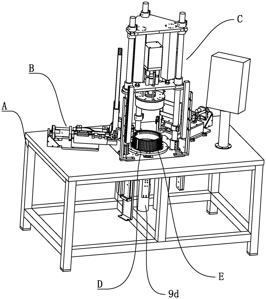
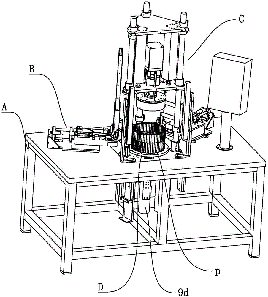
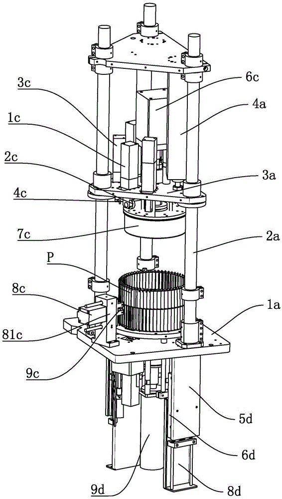
[0048] The overall schematic diagram of embodiment is referring to appendix figure 1 , mainly includes the frame A, the mold E mounted on the base plate 1a of the frame A, the motor 9d for driving the mold E to rotate, the positioning mechanism D for positioning the lower gland 2p of the impeller P, and the positioning mechanism D for positioning the blade 1p is fed into the slot of the mold E by the pushing mechanism B and the rolling riveting mechanism C which rivets the lower ...


PUM


Abstract

The invention discloses an impeller assembly machine which comprises a machine base, a mold arranged on the machine base and allowing blades of an impeller to be inserted therein, a push mechanism arranged on the machine base and used for pushing the blades to the mold and a rolling and riveting mechanism for riveting the impeller. The height of the mold is equal to half of the length of the blades. The rolling and riveting mechanism comprises an upper riveting mechanism for bending and fixing an upper gland of the impeller and insertion pieces of the blades and a middle riveting mechanism for riveting the blade in the middle of the impeller and a reinforcing partition plate arranged in the middle of the impeller. The middle riveting mechanism capable of riveting the reinforcing partition plate of the double-layer impeller is additionally arranged on the basis that only the upper gland and a lower gland of the impeller can be riveted to the impeller, so that only one working procedure is added without affecting the original riveting efficiency, and the machining efficiency of the double-layer impeller is improved greatly.

Description

technical field [0001] The invention relates to an impeller assembly device of a range hood, more specifically, to an impeller assembly machine. Background technique [0002] The common vane-type impeller used for fans or range hoods usually includes a plurality of blades arranged at intervals along the annular array in sequence, and upper glands respectively arranged on the top of the annular distribution blades and arranged on the annular distribution blades. The lower gland at the bottom of the blade, the upper and lower ends of the blade of the impeller are formed with inserts, the inserts pass through the slot holes of the upper gland and the slots of the lower gland, and the inserts are bent and pressed against the upper gland and on the end face of the lower gland. [0003] At present, the blade installation process of the above-mentioned blade impeller is mostly realized by manual blade insertion, that is, one end of the punched blade is manually inserted into the l...

Claims


Application Information

Patent Timeline
IPC IPC(8): F04D29/60
CPCF04D29/601
Inventor 贾世强
Owner 南通市京山锦纶有限公司
Why Eureka
Try Eureka