Light ray control method of turning auxiliary warning lamp

A light control and warning light technology, applied in lighting auxiliary devices, light sources, lampshades, etc., to achieve a large warning range, ensure fixed effect, and improve connection reliability.

Active Publication Date: 2016-04-13
重庆熠美实业发展有限公司
View PDF5 Cites 1 Cited by
  • Summary
  • Abstract
  • Description
  • Claims
  • Application Information

AI Technical Summary

Problems solved by technology

[0005] Aiming at the deficiencies of the above-mentioned prior art, the technical problem to be solved by the present invention is: how to provide a light control method for turning auxiliary warning lights that is simple to implement, can generate a larger warning range, and improve warning effects, so as to avoid waste and save energy Effect

Method used


Image

  • Light ray control method of turning auxiliary warning lamp
  • Light ray control method of turning auxiliary warning lamp
  • Light ray control method of turning auxiliary warning lamp

Examples


Embodiment approach

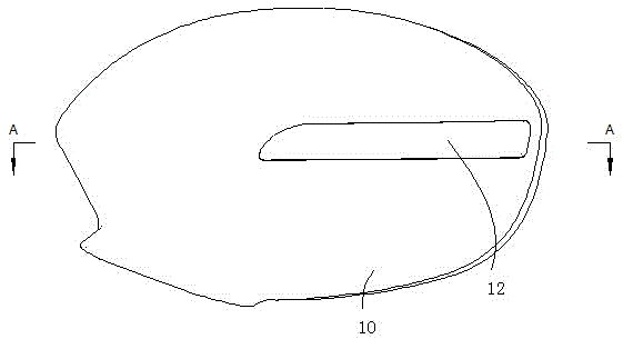
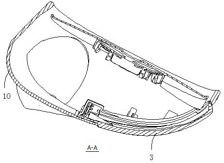
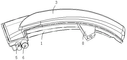
[0044] Optimum implementation mode: a method for controlling the light of turning auxiliary warning lights, the key point of which is that the lampshade is set as an exposed arc-shaped block structure that is curved in the length direction as a whole, and the LED light source is arranged facing the inner end of the lampshade, and After most of the direct light of the LED light source is injected from the inner end of the lampshade, it is reflected in the inner space of the lampshade for many times and then shines out from the end face of the lampshade away from the LED light source, and a small part of the scattered light of the LED light source is reflected in the lampshade. Exposed from the rest of the lampshade.

[0045] In this way, this method only needs an LED light source at one position, which can produce a warning effect with a larger warning range. At the same time, the brightness of the warning light is different at different positions on the outer surface of the lam...


PUM


Abstract

The invention discloses a light ray control method of a turning auxiliary warning lamp. The light ray control method is characterized in that a lamp cover is set as an integral exposed arc block structure bent in the length direction; an LED light source is aligned to the inner end of the lamp cover; after most direct light of the LED light source is emitted in from the inner end of the lamp cover, the light is transmitted out from the end surface of one end, far from the LED light source, of the lamp cover after multiple times of total reflection in an internal space of the lamp cover; and few scattering light rays of the LED light source are reflected in the lamp cover to be transmitted out from other positions of the lamp cover. The light ray control method has the advantages of simple actuation, capability of adopting fewer light sources to generate a wider warning range and improvement of warning effect, and achieves the effects of waste prevention and energy saving.

Description

technical field [0001] The invention relates to an automobile accessory, in particular to a method for controlling the light of a turning auxiliary warning light. Background technique [0002] Outside rearview mirrors are set on both sides of the front of the car to help the driver observe the situation behind the car body to ensure driving safety. At the same time, both sides of the car will also consider setting turn signals, which are used to turn on when the motor vehicle is turning to remind the important indicator lights of front, rear, left, right vehicles and pedestrians. [0003] Existing general automobile turn signals are installed in the outermost positions on the left and right sides of the front end and the rear end, but in fact the exterior rearview mirror of the vehicle is the outermost member of the vehicle body. Therefore, in the prior art, a kind of exterior rearview mirror with turning signal has occurred. In this way, setting the side turn signals on t...

Claims


Application Information

Patent Timeline
Patent Type & Authority Applications(China)
IPC IPC(8): F21S8/10F21V3/02F21V19/00F21V3/04F21V15/01F21V17/10F21V21/00F21W101/12F21Y115/10
CPCF21S43/14F21S43/50F21V3/02F21V3/062F21V15/01F21V17/101F21V19/001F21V19/0025F21V21/00F21W2103/20
Inventor 周朝伦胡数松
Owner 重庆熠美实业发展有限公司
Why Eureka
Try Eureka