A carbon dioxide cracker and filling method

A technology of carbon dioxide and liquid carbon dioxide, which is applied in blasting and other directions, can solve the problems of low utilization rate of liquid carbon dioxide, unfavorable operation of staff, and restrictions on the adjustment and change of conductive structure, so as to improve the convenience of operation, improve the efficiency of filling, and conduct electricity reliably Sexual Enhancement Effects

Active Publication Date: 2019-06-11
BEIJING CHINA COAL MINE ENG CO LTD
View PDF4 Cites 0 Cited by
  • Summary
  • Abstract
  • Description
  • Claims
  • Application Information

AI Technical Summary

Problems solved by technology

The cut-off valve structure is located inside the housing of the valve body 11 on the one hand, which is not conducive to the operation of the staff. On the other hand, as figure 1 As shown, since the shut-off valve 20 is arranged along the central axis of the valve body 11 and is close to the conductive path in the filling valve, it may cause an open circuit or short circuit of the conductive path, which has potential safety hazards. Moreover, the existence of the shut-off valve 20 The space that the electrode structure of the conductive path can occupy is greatly reduced, which limits the adjustment and change of the conductive structure
In addition, since the shut-off valve 20 is arranged along the central axis of the valve body 11, the size of the shut-off valve is limited, thereby limiting the stiffness of the shut-off valve.
[0004] In addition, in the traditional filling method, it needs three steps of evacuating the cracker, cooling, and filling to complete the filling of liquid carbon dioxide. This method is complex in operation, low in efficiency, and low in utilization of liquid carbon dioxide.

Method used


Image

  • A carbon dioxide cracker and filling method
  • A carbon dioxide cracker and filling method
  • A carbon dioxide cracker and filling method

Examples


Embodiment Construction

[0021] The technical solutions in the embodiments of the present invention will be clearly and completely described below in conjunction with the accompanying drawings in the embodiments of the present invention. Obviously, the described embodiments are only some, not all, embodiments of the present invention. Based on the embodiments of the present invention, all other embodiments obtained by persons of ordinary skill in the art without creative efforts fall within the protection scope of the present invention.

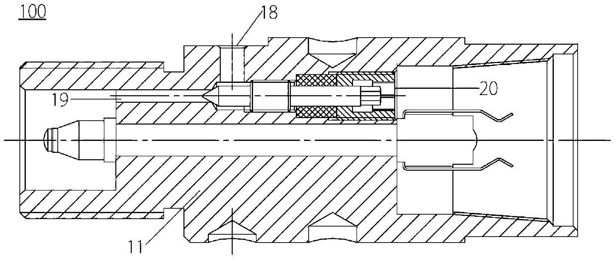
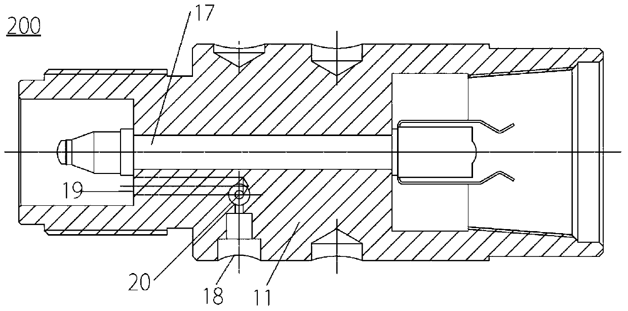
[0022] A cracker according to an embodiment of the present invention, the cracker includes a filling valve, a heating device, a liquid storage tube, a sealing gasket, a constant pressure shear piece and a release tube. Filling valves such as figure 2 shown.

[0023] Wherein, the filling valve 200 has a valve body 11 and a conduction portion 17 located in the valve body 11, the conduction portion 17 is used to input power from one end of the filling valve to the oth...


PUM


Abstract

The invention discloses a carbon dioxide fracturing device and a filling method. The carbon dioxide fracturing device comprises a filling valve, a heating device, a liquid storage pipe, a sealing pad, a fixed-pressure shearing piece and a release pipe. The filling valve is provided with a valve body and a breakover portion located in the valve body. The breakover portion is used for inputting power to the other end of the filing valve from one end of the filling valve. The valve body is provided with an input opening for inputting liquid carbon dioxide, an output opening for outputting liquid carbon dioxide and a stop valve. A passageway is formed between the input opening and the output opening. The stop valve is used for controlling connection and disconnection of the passageway. One end of the stop valve is located on the outer surface of the valve body and the other end of the stop valve is located on the passageway. The filling valve is easy and convenient to operate, the filling method adopting the filling valve is easy and convenient to implement, the breakover structure design space is large, and filling efficiency is high.

Description

technical field [0001] The invention belongs to the field of blasting devices, in particular to a carbon dioxide cracker and a filling method. Background technique [0002] In the mining of mineral resources, the high-pressure gas blasting technology of carbon dioxide fracturing is a new type of physical blasting technology at present. The carbon dioxide cracker uses liquid carbon dioxide to absorb heat and gasify, and the volume expands rapidly to generate high pressure, causing the coal (rock) body to break or crack. Carbon dioxide crackers replace explosives and can be used for blasting coal drop, gas comprehensive treatment, roof treatment, rock burst treatment, outburst elimination, top coal weakening, stone gate coal removal, roadway bottom drum treatment, coal bunker clearing, etc. Used for coal seam fracturing and permeability enhancement, it can significantly increase the gas permeability of coal seams, solve the problems of difficult and frequent over-limit gas ex...

Claims


Application Information

Patent Timeline
Patent Type & Authority Patents(China)
IPC IPC(8): F42D1/00F42D3/04
CPCF42D1/00F42D3/04
Inventor 龚建宇王子雷贺超邱天德何勇俊刘杰刘传培王剑刘志生王建秋宾雄志詹德帅李昂高素英
Owner BEIJING CHINA COAL MINE ENG CO LTD
Why Eureka
Try Eureka