
Sulfur dioxide infrared detection device and method

A sulfur dioxide and infrared detection technology, which is applied in measuring devices, material analysis through optical means, instruments, etc., can solve the problems of deviation, high cost, and complexity of monitoring results, and achieve the goal of improving system sensitivity, expanding application range, and reducing impact Effect

Inactive Publication Date: 2016-04-13
KUNMING QINRUI TECH CO LTD
View PDF10 Cites 7 Cited by
  • Summary
  • Abstract
  • Description
  • Claims
  • Application Information

AI Technical Summary

Problems solved by technology

In practical applications, water vapor in the air also has absorption characteristics for infrared light near 7300 nanometers. The attenuation of infrared light flux caused by water vapor and environmental interference often exceeds the attenuation of infrared light flux caused by sulfur dioxide gas. If the ideal The device and concentration calculation method that can accurately detect sulfur dioxide in the laboratory environment are applied to the real-time online monitoring of sulfur dioxide concentration in the actual air, which will cause the monitoring results to deviate far from the actual situation.
It is for this reason that the existing real-time online monitoring system for sulfur dioxide needs to be equipped with a complex and high-cost pretreatment system for drying, dust removal, and cleaning treatment of the detected gas, which greatly improves the real-time online monitoring of sulfur dioxide. The cost and maintenance cost of the monitoring system restrict the application range of real-time online monitoring of sulfur dioxide

Method used


Image

  • Sulfur dioxide infrared detection device and method
  • Sulfur dioxide infrared detection device and method
  • Sulfur dioxide infrared detection device and method

Examples


Embodiment Construction

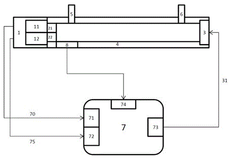
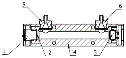
[0020] Such as figure 1 Shown is the principle block diagram of the sulfur dioxide infrared detection device of the present invention. As shown in the figure, the sulfur dioxide infrared detection device of the present invention includes an infrared light source 3, a dual-element pyroelectric infrared detector 1, a gas channel unit 11 of the dual-element pyroelectric infrared detector 1, and a dual-element pyroelectric infrared detector 1 reference channel unit 12, first narrow-band filter 21, second narrow-band filter 22, air chamber 4, air chamber inlet port 5, air chamber outlet port 6, main control circuit board 7, humidity sensor 8 .

[0021] In the embodiment of the present invention, the center of the passband is 7300 nanometers, and the first optical filter 21 with a half-peak width of 80 nanometers is tightly bonded to the gas channel unit 11 of the binary pyroelectric infrared detector 1; The second optical filter 22 with a diameter of 3900 nanometers and a half wa...


PUM

PropertyMeasurementUnit
Wavelengthaaaaaaaaaa

Abstract

The present invention relates to a sulfur dioxide infrared detection device and method, and the sulfur dioxide infrared detection device comprises an infrared light source, a dual-unit pyroelectric infrared detector, a first narrowband light filter, a second narrowband light filter, a gas chamber, a humidity sensor and a main control circuit board. Infrared light emitted by the infrared light source mounted on one end of the gas chamber is absorbed by sulfur dioxide gas so as to cause reduction of an output signal of the pyroelectric infrared detector mounted on the other end of the gas chamber. Compared with the prior art, the sulfur dioxide infrared detection device and method can significantly reduce the impact of water vapor on sulfur dioxide infrared detection devices to improve system sensitivity, significantly reduce the cost of sulfur dioxide real-time online monitoring systems of chemical companies, and are in favor of further expanding of the scope of application of real-time online monitoring of sulfur dioxide.

Description

technical field [0001] The invention relates to pollution monitoring of gas discharge, in particular to a sulfur dioxide infrared detection device and method. Background technique [0002] Sulfur dioxide SO2 is one of the main pollutants in the atmosphere and an important indicator to measure whether the atmosphere is polluted. With the continuous improvement of environmental protection awareness, real-time online monitoring of the concentration of sulfur dioxide SO2 gas in the atmosphere has become more and more necessary. Due to the low content of sulfur dioxide SO2 gas in the atmosphere, the sensitivity of the sulfur dioxide SO2 gas sensor is required to be high. At present, the sulfur dioxide monitoring system commonly used is usually based on electrochemical sensors to detect the concentration of sulfur dioxide. Although there are currently SO2 sensors capable of detecting ppm or even ppb levels of sulfur dioxide, the higher the sensitivity, the easier it is to poison,...

Claims


Application Information

Patent Timeline
IPC IPC(8): G01N21/3504
CPCG01N21/3504
Inventor 赵捷普朝光
Owner KUNMING QINRUI TECH CO LTD
Learn More