Eureka AIR delivers breakthrough ideas for toughest innovation challenges, trusted by R&D personnel around the world.

Phase pulse-type laser range finding method

A laser ranging and pulsed technology, applied in the field of phase pulsed laser ranging, can solve the problems of short measuring range, poor anti-interference ability, increased measurement time and cost, and achieve low cost, strong anti-interference ability, and measurement fast effect

Active Publication Date: 2016-04-13
米德克传感器(上海)有限公司
View PDF3 Cites 7 Cited by
  • Summary
  • Abstract
  • Description
  • Claims
  • Application Information

AI Technical Summary

Problems solved by technology

Using more rulers can improve the anti-noise ability of the system, but at the cost of increasing measurement time and cost
Using too few rulers may lead to problems such as short measuring range and poor anti-interference ability

Method used


Image

  • Phase pulse-type laser range finding method
  • Phase pulse-type laser range finding method
  • Phase pulse-type laser range finding method

Examples


Embodiment

[0083] In order to obtain the first phase difference of various frequency components in the first transmit pulse signal whose frequency F1 is 7.5 MHz, the following steps are adopted:

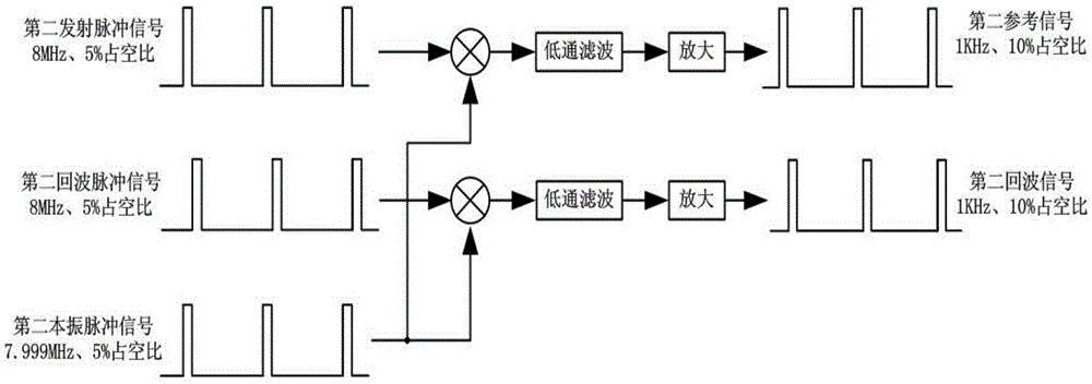
[0084] (1), such as figure 1 As shown, the first transmit pulse signal with a duty cycle of 5% and the frequency F1 of 7.5MHz and the first local oscillator pulse signal of (F1-1KHz)=7.499MHz are obtained through frequency mixing, low-pass filtering, and amplification in sequence The first reference signal; the first echo pulse signal with a frequency F1 of 7.5MHz and the first local oscillator pulse signal of (F1-1KHz)=7.499MHz are sequentially processed through frequency mixing, low-pass filtering, and amplification to obtain the first echo signal;

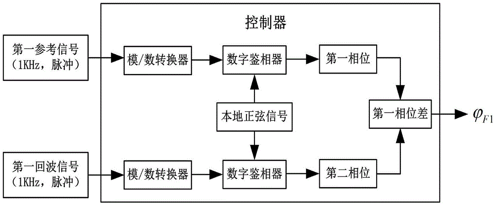
[0085] (2), such as figure 2 As shown, the first reference signal is sent to the controller, and the controller performs analog-to-digital conversion processing on the first reference signal and realizes phase detection with the 1KHz local sin...


PUM


Abstract

The invention discloses a phase pulse-type laser range finding method. The method includes the following steps: S1, obtaining a first phase difference [phi]F1 of various frequency components among first emission pulse signals with the frequency of F1MHz, and obtaining a second phase difference [phi]F2 of various frequency components among second emission pulse signals with the frequency of F2MHz; S2, conducting difference operation on the first phase difference and the second phase difference, and obtaining a phase difference [phi]0 of target modulation frequencies, wherein [phi]0=[phi]F2-[phi]F1; and S3, substituting [phi]0 into a range finding formula L=C / 2[phi]0, and obtaining a corresponding laser range finding distance L. According to the method, a duty ratio of both the first emission pulse signals and the second emission pulse signals is 5%-10%, 5MHz<F1<20MHz, and 5MHz<F2<20MHz. The method has the advantages that the cost is low, the anti-interference capability is high, and the measuring speed is fast.

Description

technical field [0001] The invention relates to the field of laser ranging, and more specifically, the invention relates to a method for phase pulse laser ranging. Background technique [0002] The traditional phase laser range finder uses continuous wave as the emission excitation, and uses different emission frequencies in different time periods. Using more rulers can improve the anti-noise ability of the system, but at the expense of increased measurement time and cost. Using too few rulers may lead to problems such as short measuring range and poor anti-interference ability. In the prior art, generally multiple measuring rulers (>4) are used to ensure the measuring range and the accuracy at the same time. Contents of the invention [0003] Aiming at the deficiencies in the above-mentioned technologies, the present invention provides a phase pulse laser ranging method, which adopts two emission pulse signals with low duty cycle and different frequencies as the emis...

Claims


Application Information

Patent Timeline
IPC IPC(8): G01S17/08
CPCG01S17/08
Inventor 何友仁
Owner 米德克传感器(上海)有限公司
Why Eureka
Eureka Blog
Learn More