
Method for calculating crack anisotropism gradient

An anisotropy and gradient technology, applied in seismic signal processing and other directions, can solve the problems of accuracy and reliability of inversion results, low signal-to-noise ratio of effective reflection signals, etc.

Active Publication Date: 2016-04-13
CHINA PETROLEUM & CHEM CORP +1
View PDF7 Cites 2 Cited by
  • Summary
  • Abstract
  • Description
  • Claims
  • Application Information

AI Technical Summary

Problems solved by technology

Although the pre-stack azimuth data is used as the input data, the amplitude of the seismic wave varies with the offset when collected in the field, but the signal-to-noise ratio of the effective reflection signal in the seismic wave data is low, and the accuracy and reliability of the inversion results are limited. The direct impact of previous data

Method used


Image

  • Method for calculating crack anisotropism gradient
  • Method for calculating crack anisotropism gradient
  • Method for calculating crack anisotropism gradient

Examples


Embodiment Construction

[0037] The implementation of the present invention will be described in detail below in conjunction with the accompanying drawings and examples, so as to fully understand and implement the process of how to apply technical means to solve technical problems and achieve technical effects in the present invention. It should be noted that, as long as there is no conflict, each embodiment and each feature in each embodiment of the present invention can be combined with each other, and the formed technical solutions are all within the protection scope of the present invention.

[0038] In addition, the steps shown in the flow diagrams of the figures may be performed in a computer system, such as a set of computer-executable instructions, and, although a logical order is shown in the flow diagrams, in some cases, the sequence may be different. The steps shown or described are performed in the order herein.

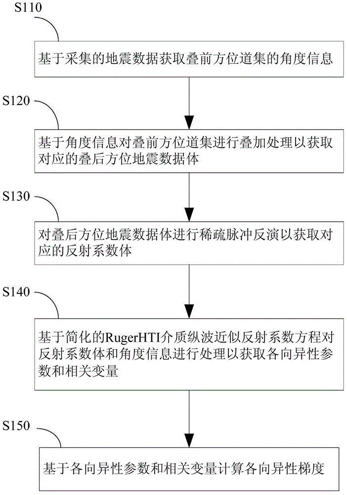
[0039] like figure 1 Shown is a flow chart of a method according to an embo...


PUM


Abstract

The invention discloses a method for calculating crack anisotropism gradient. The method comprises: based on acquired seismic data, obtaining angle information of pre-stack azimuth gather; based on the angle information, performing superposition processing on the pre-stack azimuth gather, to obtain corresponding post-stack azimuth seismic data cube; performing sparse pulse inversion on the post-stack azimuth seismic data volume, to obtain corresponding reflection coefficient body; based on a simplified Ruger HTI medium longitudinal wave approximate reflection coefficient equation, processing the reflection coefficient body and the angle information, to obtain a longitudinal wave variable coefficient difference value of the upper layer and the lower layer of a HTI medium and correlated variables; and based on the longitudinal wave variable coefficient difference value of the upper layer and the lower layer of the HTI medium and the correlated variables, calculating the anisotropism gradient. The method is based on post-stack azimuth data, and the high-quality part of the seismic data is selected to be used as inversion input data, thereby preventing direct influence of post-stack azimuth data on calculation results. The inversion method is high in stability and high in signal to noise ratio.

Description

technical field [0001] The invention relates to the technical field of geophysics, in particular to a method for calculating the anisotropic gradient of formation fractures. Background technique [0002] In the study of fractured reservoirs, it is necessary to obtain quantitative fracture parameters in the fracture prediction process. Fracture parameters are often chosen to reflect the anisotropic gradient that can well reflect the intensity and direction of fracture development. Since the order of magnitude of anisotropy parameters is much smaller than that of seismic data, most studies choose to simplify the approximate reflection coefficient equation of the RugerHTI medium P-wave, and use the prestack azimuth data as the input data of the equation to invert the equation to obtain various Anisotropic gradient. Although the pre-stack azimuth data is used as the input data, the amplitude of the seismic wave varies with the offset when collected in the field, but the signal...

Claims


Application Information

Patent Timeline
IPC IPC(8): G01V1/28
Inventor 张克非肖鹏飞李呈呈周单须振华许凯
Owner CHINA PETROLEUM & CHEM CORP
Learn More