Metal mesh dual touch sensor, touch module and touch electronic device
A metal mesh and dual-touch technology, which is applied in the direction of instruments, electrical digital data processing, and data processing input/output processes, can solve the problems of inability to better identify the position information of touch points, slow response speed of touch products, Increased I/O interfaces and other issues to achieve the effect of simple structure, low material impedance, and reasonable wiring
- Summary
- Abstract
- Description
- Claims
- Application Information
AI Technical Summary
Problems solved by technology
Method used
Image
Examples
Embodiment 1
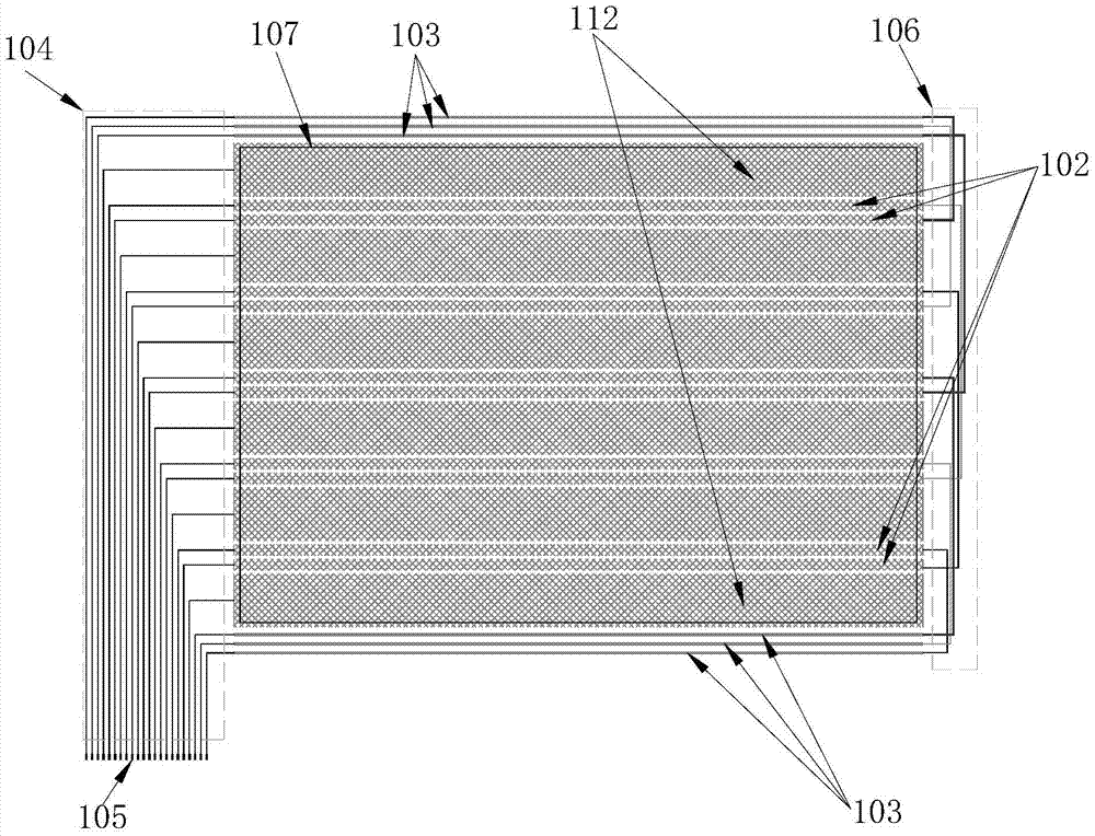
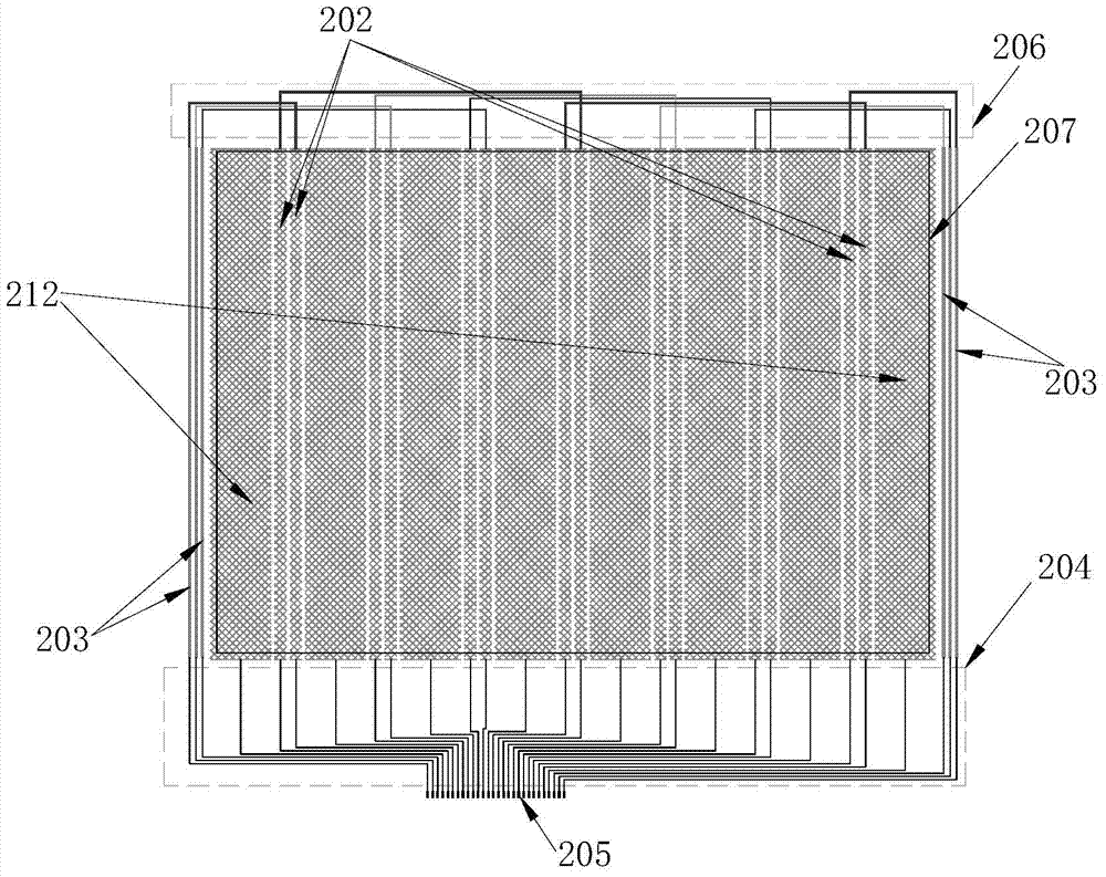
[0059] Such as Figure 1 to 2 Shown: It is the metal mesh dual touch sensor provided by Embodiment 1 of the present invention. The metal mesh dual touch sensor not only has the advantage of low material impedance, but also can realize the design of a larger size touch sensor. The characteristics of reasonable wiring, simple structure and high touch efficiency, as well as the functions of capacitive touch and electromagnetic touch, simplify the structure of the metal mesh double touch sensor and reduce the manufacturing cost at the same time. It includes metal mesh double A touch sensing array. The metal mesh dual touch sensor includes a metal mesh group in a first direction and a metal mesh group in a second direction, between the direction of the metal mesh group in the first direction and the direction of the metal mesh group in the second direction There is a first angle greater than 0°, and the metal mesh group in the first direction and the metal mesh group in the second di...
Embodiment 2
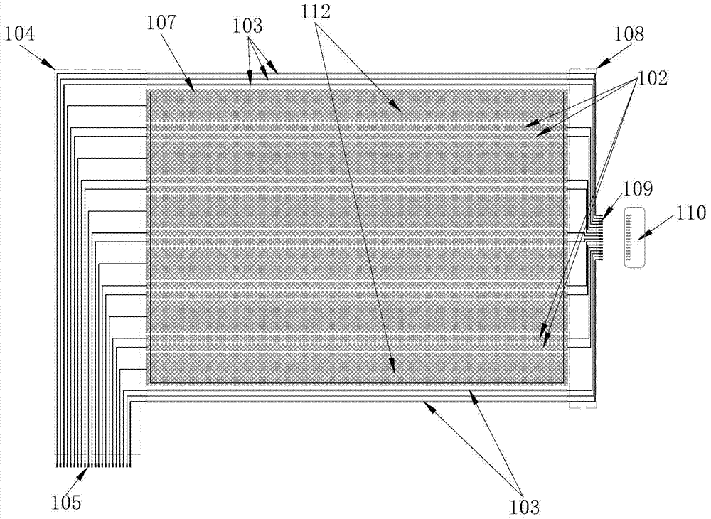
[0067] Such as image 3 with Figure 4 Shown is the metal mesh dual touch sensor provided in Embodiment 2 of the present invention. The difference from Embodiment 1 is: the first-direction electromagnetic touch metal mesh in the first-direction metal mesh group in this embodiment 2 The right end of 102 is provided with a first wiring 108, and the end of the first wiring 108 is provided with a third signal extraction interface 109, and the third signal extraction interface is connected to the first transfer film line 110; meanwhile, the metal mesh In the dual touch sensor, the outer side of the upper end and the outer side of the lower end of the metal mesh group in the first direction corresponding to the electromagnetic pen touch effective area 107 or corresponding to the display screen visible area 107 are horizontally provided with three parallel first solid conductors 103, so A first signal lead-out line is provided at the left end of the first solid conductor, a first signa...
Embodiment 3
[0071] Such as Figure 5 to Figure 10 Shown is the touch module provided by Embodiment 3 of the present invention, in which: Figure 5 It is a schematic structural diagram of the first-direction metal mesh group and the first substrate in the touch module provided by Embodiment 3 of the present invention, Image 6 It is a schematic diagram of the structure of the second-direction metal mesh group combined with the second substrate in the touch module provided in Embodiment 3 of the present invention. The touch module provided in Embodiment 3 has a double-layer structure, which includes a first substrate 101 and The second substrate 201, the first substrate 101 is arranged above the second substrate 201, the first direction metal mesh group in the metal mesh double touch sensor is arranged on the upper surface of the first substrate 101, the metal mesh double touch sensor The second direction metal mesh set in the second direction is set on the upper surface of the second substrat...
PUM
 Abstract
Description
Claims
Application Information
 - R&D
- Intellectual Property
- Life Sciences
- Materials
- Tech Scout
- Unparalleled Data Quality
- Higher Quality Content
- 60% Fewer Hallucinations
Browse by: Latest US Patents, China's latest patents, Technical Efficacy Thesaurus, Application Domain, Technology Topic, Popular Technical Reports.
© 2025 PatSnap. All rights reserved.Legal|Privacy policy|Modern Slavery Act Transparency Statement|Sitemap|About US| Contact US: help@patsnap.com


