
Improved cryogenic box

A low temperature box and improved technology, applied in cryostats, laboratory utensils, fluid controllers, etc., can solve the problems of insignificant ventilation and cooling effect, slow temperature adjustment response, etc., to ensure uniformity and improve temperature adjustment speed. Effect

Inactive Publication Date: 2016-04-20
SUZHOU DONGHUA TESTING INSTR
View PDF10 Cites 1 Cited by
  • Summary
  • Abstract
  • Description
  • Claims
  • Application Information

AI Technical Summary

Problems solved by technology

[0003] The main technical problem to be solved by the present invention is to provide an improved low-temperature box, which has a reasonable design and a simple structure, and solves the problem that the effect of ventilation and refrigeration is not obvious and the response of temperature regulation is slow

Method used


Image

  • Improved cryogenic box

Examples


Embodiment Construction

[0010] The preferred embodiments of the present invention will be described in detail below in conjunction with the accompanying drawings, so that the advantages and features of the present invention can be more easily understood by those skilled in the art, so as to define the protection scope of the present invention more clearly.

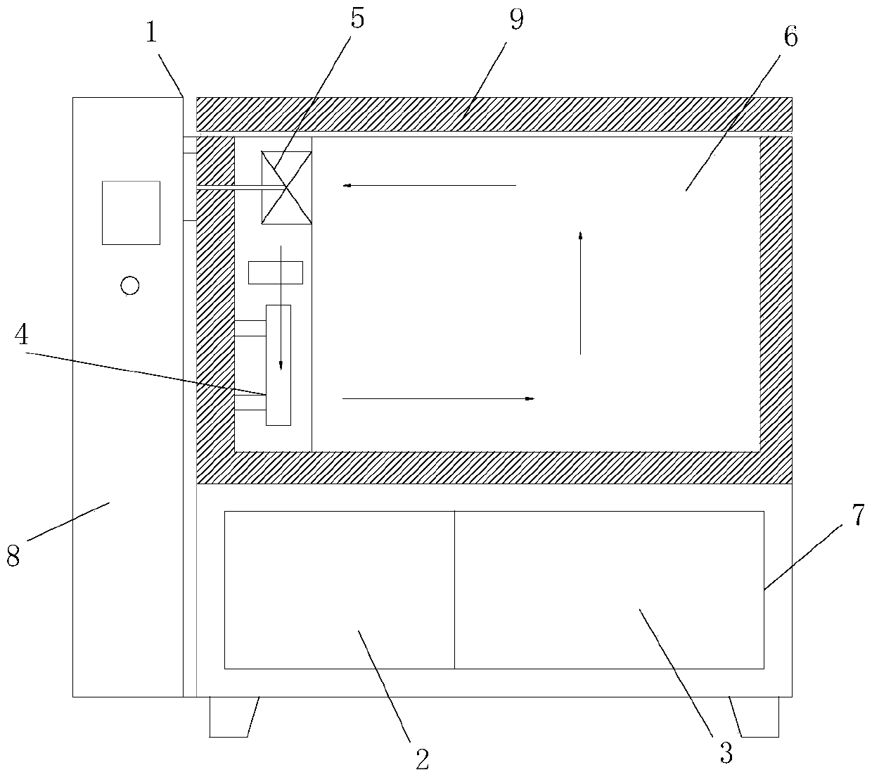
[0011] Please refer to the attached figure 1 , the embodiment of the present invention includes:

[0012] An improved low-temperature box, including a case 1, a refrigeration device 2, an air compression device 3, a pre-embedded copper pipe 4 and a circulating air duct 5; the case includes a working room 6 and a control room 7; the working room 6 is located in Above the control room 7; the inner wall of the working room 6 is a thermal insulation board 9; the inner wall of the working room 6 is also provided with the embedded copper pipe 4; the inner wall of the working room 6 The circulating air duct 5 is also provided; the circulating air duct ...


PUM


Abstract

The invention provides an improved cryogenic box which comprises a machine case, a refrigeration device, an air compression device, an embedded copper pipe and a circulating air channel. The machine case comprises a working chamber and a control chamber. The working chamber is located above the control chamber. The inner wall of the working chamber is heat-preservation heat-insulation boards. The embedded copper pipe is further arranged on the inner wall of the working chamber. The circulating air channel is further arranged on the inner wall of the working chamber. The circulating air channel forms a circulating path along the inner wall of the working chamber. The air compression device and the refrigeration device are arranged in the control chamber. The refrigeration device is connected with the embedded copper pipe. The air compression device is connected with the circulating air channel.

Description

technical field [0001] The invention relates to the field of building material testing equipment, in particular to an improved low-temperature box. Background technique [0002] The low temperature test chamber can be used to assess and determine the adaptability of electrical and electronic products or materials for storage and use under temperature cycle changes and low temperature environmental conditions on the product surface. The equipment uses forced air circulation to maintain the uniformity of temperature in the working room. In order to limit the influence of radiation, the difference between the temperature of each part of the inner wall of the equipment and the temperature specified in the test is not more than 8%, and the test sample will not be directly radiated by the heating and cooling elements in the equipment. In order to ensure the cooling rate and minimum temperature requirements of the test chamber, the refrigeration system of this test chamber adopts ...

Claims


Application Information

Patent Timeline
IPC IPC(8): B01L1/02B01L7/00
CPCB01L1/025B01L7/50B01L2300/0809B01L2300/1838B01L2300/1883B01L2300/1894B01L2400/0475
Inventor 王毅成
Owner SUZHOU DONGHUA TESTING INSTR
Learn More