3D printing method of metal ceramic functional gradient part in alternating magnetic field

A cermet and alternating magnetic field technology, which is applied in the direction of improving energy efficiency, process efficiency, additive manufacturing, etc., and can solve problems such as the inability to prepare intermetallic or cermet gradient parts

Active Publication Date: 2016-04-20
JILIN UNIV
View PDF7 Cites 19 Cited by
  • Summary
  • Abstract
  • Description
  • Claims
  • Application Information

AI Technical Summary

Problems solved by technology

[0003] The purpose of the present invention is to provide a 3D printing method for metal-ceramic functional gradient parts using alternating magnetic field for the existing metal 3D printing technology, which can only prepare single-material metal parts and cannot prepare metal-ceramic gradient parts.

Method used


Image

  • 3D printing method of metal ceramic functional gradient part in alternating magnetic field
  • 3D printing method of metal ceramic functional gradient part in alternating magnetic field
  • 3D printing method of metal ceramic functional gradient part in alternating magnetic field

Examples


specific example 1

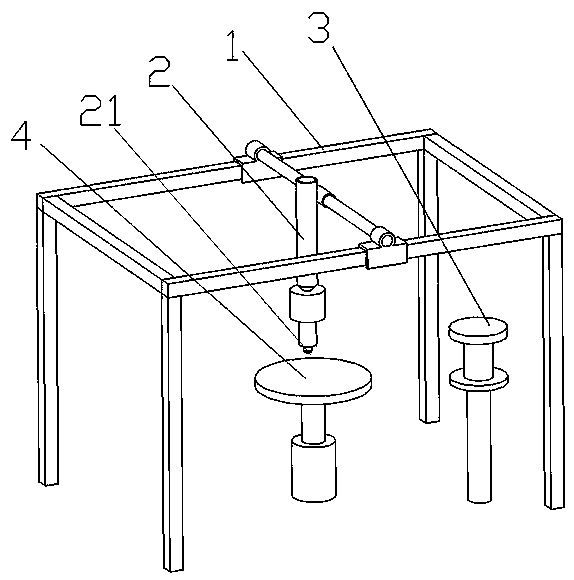
[0051] see figure 1 , Figure 5 , Image 6 with Figure 7 As shown, one of the present invention is a 3D printing method of cermet functionally graded parts in an alternating magnetic field, and the steps of the method are as follows:

[0052] One: The preparation of the mixed slurry, the cermet powder and the polymer binder are evenly mixed and then heated, the mixed slurry melts at 170°C and solidifies rapidly at room temperature;

[0053] The composition and mass percent of the mixed slurry are as follows:

[0054] 60% metal ceramic powder, 40% polymer binder;

[0055] The composition and mass percentage of the cermet powder are as follows:

[0056] Metal powder 33%, ceramic powder 67%;

[0057] The metal powder: 1-90 μm, with a median particle size of 40 μm;

[0058] The metal powder material is Cu;

[0059] The ceramic powder: 1-90 μm, with a median particle size of 40 μm;

[0060] The ceramic powder material is Al2O3;

[0061] The composition and mass percentag...

specific example 2

[0068] see figure 1 , Figure 5 , Image 6 with Figure 7 As shown, one of the present invention is a 3D printing method of cermet functionally graded parts in an alternating magnetic field, and the steps of the method are as follows:

[0069] One: The preparation of the mixed slurry, the cermet powder and the polymer binder are evenly mixed and then heated. The metal slurry melts at 200 ° C and solidifies rapidly at room temperature;

[0070] The composition and mass percent of the mixed slurry are as follows:

[0071] Metal-ceramic powder 63%, polymer binder 37%;

[0072] The composition and mass percentage of the cermet powder are as follows:

[0073] Metal powder 35%, ceramic powder 65%;

[0074] The metal powder: 1-90 μm, with a median particle size of 40 μm;

[0075] The metal powder material is Fe;

[0076] The ceramic powder: 1-90 μm, with a median particle size of 40 μm;

[0077] The ceramic powder material is SiC;

[0078] The composition and mass percentag...


PUM

PropertyMeasurementUnit
thicknessaaaaaaaaaa
thicknessaaaaaaaaaa
thicknessaaaaaaaaaa

Abstract

The invention discloses a 3D printing method of a metal ceramic functional gradient part in an alternating magnetic field. A metal material with excellent electric conductivity in the alternating magnetic field generates induction current inside due to continuous change of a magnetic field; based on different responses of the metal material with excellent electric conductivity and ceramic not easy to conducting electricity to the alternating magnetic field, the directional distribution of the metal materials is controlled through the alternating magnetic field in the printing process; the magnitude of driving force is changed through changing alternating current intensity and current frequency; the metal ceramic functional gradient part is prepared; the 3D printing of the metal ceramic gradient part in the alternating magnetic field is realized; the gradient material distribution can be realized in any space position; the material and the equipment cost are saved; and the 3D printing method is suitable for wide popularization and application.

Description

technical field [0001] The invention belongs to the 3D printing technology in the field of mechanical manufacturing, and in particular relates to a 3D printing method for metal-ceramic functional gradient parts in an alternating magnetic field. Background technique [0002] 3D printing is a rapid prototyping technology that uses digital models as the driving source to construct the spatial form of objects by layer-by-layer printing. In recent years, with the development of additive manufacturing to functional parts manufacturing, metal additive manufacturing has also reached an extreme. With the development of the earth, the existing metal 3D printing technologies include selective laser sintering technology (SLS), selective laser melting technology (SLM), laser rapid prototyping technology (LRF) or laser stereoforming technology (LSF). Most of the laser operations remain in the homogeneous processing of single materials, and it is impossible to realize the forming of parts ...

Claims


Application Information

Patent Timeline
Patent Type & Authority Applications(China)
IPC IPC(8): B22F3/105
CPCB22F2202/05B22F2207/17B22F10/00B22F10/18B22F12/226B22F12/53B22F10/50Y02P10/25
Inventor 周雪莉刘庆萍任露泉赵彻宋正义李冰倩刘清荣李卓识刘慧力于征磊
Owner JILIN UNIV
Why Eureka
Try Eureka