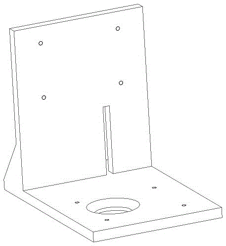
Installation jig and installation technology for guide rails of numerically-controlled machine tool

A technology of CNC machine tools and guide rails, applied in the direction of manufacturing tools, metal processing equipment, metal processing machinery parts, etc., can solve the problems of difficult production and assembly, small profit margins, etc., and achieve the effects of stable installation accuracy, improved quality, and fast speed

Inactive Publication Date: 2016-04-20
安徽省皖凯机械有限公司
View PDF6 Cites 3 Cited by
  • Summary
  • Abstract
  • Description
  • Claims
  • Application Information

AI Technical Summary

Problems solved by technology

However, because the production and assembly of micro-NC machine tools is more difficult than that of medium-sized CNC machine tools, many domestic companies that produce CNC machine tools are unwilling to produce micro-NC machine tools
Due to its small profit margin, micro-NC machine tools are destined to minimize and minimize the processing difficulty of the base and parts of micro-NC machine tools in the production and assembly process of micro-NC machine tools. Therefore, the existing technology can no longer satisfy people. There is an urgent need for a high-efficiency installation fixture and installation process, that is, a CNC machine tool guide rail installation fixture and installation process, which can quickly and accurately install the X-axis and Y-axis guide rails of micro-NC machine tools. And at the same time reduce the processing difficulty of the base of the micro CNC machine tool

Method used


Image

  • Installation jig and installation technology for guide rails of numerically-controlled machine tool
  • Installation jig and installation technology for guide rails of numerically-controlled machine tool

Examples


Embodiment Construction

[0017] Such as figure 1 As shown, a guide rail installation fixture for CNC machine tools, including an L-shaped right-angle main body (1), a positioning plate (2), a Y-axis guide rail fixing groove, (3), an X-axis guide rail fixing groove (4), and a guide rail fixing guide hole (5), fixture fixing screw holes (6); it is characterized in that the L-shaped right-angle main body (1) is ground into a 00-grade right-angle L frame made of cast iron, and a positioning plate is arranged on one side of the L-shaped right-angle main body (1) (2), the L-shaped right-angle main body (1) has a Y-axis guide rail fixing groove (3) on the bottom plate, the L-shaped right-angle main body (1) has an X-axis guide rail fixing groove (4) on the vertical plate, and the L-shaped right-angle main body ( 1) There are 8 fixture fixing screw holes (6), facing the Y-axis guide rail fixing groove (3), X-axis guide rail fixing groove (4) and guide rail fixing guide holes (5), the positioning plate ( 2) I...


PUM


Abstract

The invention provides an installation jig and an installation technology for guide rails of a numerically-controlled machine tool. The installation jig comprises an L-shaped right-angle body, a locating plate, Y-axis guide rail fixing grooves, X-axis guide rail fixing grooves, guide rail fixing guide holes and jig fixing screw holes. The installation technology comprises the steps of 1, cleaning the surface of a base of the numerically-controlled machine tool to be installed and the installation jig for the guide rails of the numerically-controlled machine tool; 2, aligning the locating plate of the installation jig for the guide rails of the numerically-controlled machine tool to one side of the base of the numerically-controlled machine tool and fixing the installation jig to the base of the numerically-controlled machine tool through eight screws M10; 3, sequentially drilling screw holes M6 in the base of the numerically-controlled machine tool by an electric hand drill through the guide rail fixing guide holes for fixing the guide rails of the numerically-controlled machine tool; 4, inserting the guide rails into the X-axis guide rail fixing grooves and the Y-axis guide rail fixing grooves respectively, and fixing the guide rails firmly through inner hexagonal socket head cap screws M6; 5, disassembling the installation jig and the screws fixing the base of the numerically-controlled machine tool and then completing installation of the X-axis guide rail and the Y-axis guide rail.

Description

technical field [0001] The invention relates to a guide rail installation jig of a numerical control machine tool, which belongs to the field of numerical control machine tools, and aims at the situation that the guide rail installation of the numerical control machine tool is difficult to calibrate, and is particularly aimed at the installation jig and installation process of the X-axis and Y-axis guide rail of the micro-numerical control machine tool. Background technique [0002] Micro CNC machine tools are becoming increasingly important in the processing of precision small parts, especially in the processing of precision parts in mobile phones, automobiles, watches and other industries. However, because the production and assembly of micro-NC machine tools is more difficult than that of medium-sized CNC machine tools, many domestic companies that produce CNC machine tools are unwilling to produce micro-NC machine tools. Due to its small profit margin, micro-NC machine t...

Claims


Application Information

Patent Timeline
Patent Type & Authority Applications(China)
IPC IPC(8): B23Q1/01
CPCB23Q1/017
Inventor 郭洪超王晖陈鹏韦永明张澳宇张杰
Owner 安徽省皖凯机械有限公司
Why Eureka
Try Eureka