Driving structure of scrap removal rod

A technology of driving structure and chip removal groove, applied in metal processing machinery parts, maintenance and safety accessories, metal processing equipment, etc., can solve the problems of reducing chip removal efficiency, etc. Effect

Active Publication Date: 2016-04-20
SUZHOU DIHILL GREEN TECH
View PDF4 Cites 3 Cited by
  • Summary
  • Abstract
  • Description
  • Claims
  • Application Information

AI Technical Summary

Problems solved by technology

However, when the chip removal rod moves in the opposite direction (opposite to the chip removal direction), if the bottom of the chip removal rod is still in contact with the bottom of the chip removal groove, metal chips may be brought back, which will reduce the efficiency of chip removal
And when the chip removal rod moves in the opposite direction (opposite to the chip removal direction), it will be resisted by the cutting fluid

Method used


Image

  • Driving structure of scrap removal rod
  • Driving structure of scrap removal rod

Examples


Embodiment Construction

[0033] The specific embodiments of the present invention will be further described below with reference to the accompanying drawings and embodiments. The following examples are only used to illustrate the technical solutions of the present invention more clearly, and cannot be used to limit the protection scope of the present invention.

[0034] The technical scheme of the specific implementation of the present invention is:

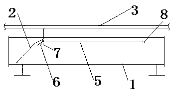
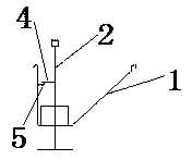
[0035] like figure 1 , figure 2 As shown, a driving structure of a chip removal rod includes:

[0036] Straight chip flute 1,

[0037] The bottom end can extend into the chip removal rod 2 at the bottom of the chip removal groove 1,

[0038] The drive rod 3 is located above the chip removal groove 1 and is hinged to the top of the chip removal rod 2, and is used to drive the chip removal rod 2 to reciprocate along the length direction of the chip removal groove 1.

[0039] The support rod 4 fixed on the chip removal rod 2,

[0040] The horizontal ...


PUM


Abstract

The invention discloses a driving structure of a scrap removal rod. The driving structure comprises a straight strip shaped scrap removal groove, the scrap removal rod, a driving rod, a supporting rod, a horizontal retaining bar, a guide bar, a limiting part and an oblique extension bar. The bottom end of the scrap removal rod is capable of extending into the bottom of the scrap removal groove; the driving rod which is positioned above the scrap removal groove is hinged to the top end of the scrap removal rod and used for driving the scrap removal rod to reciprocate along the length direction of the scrap removal groove; the supporting rod is fixed to the scrap removal rod; the horizontal retaining bar is used for supporting the supporting rod to move horizontally; the guide bar which is positioned at a first end of the retaining bar is hinged to the retaining bar and used for guiding the supporting rod to move towards the retaining bar; the limiting part is positioned below the guide bar and used for supporting the guide bar; the oblique extension bar which extends downwardly from a second end of the retaining bar is used for guiding the supporting rod to slide down gradually from the second end of the retaining bar. The driving structure of the scrap removal rod is reasonable in structure; the scrap removal rod in reverse movement can be lifted up, and consequently resistance of cutting liquid is reduced, the probability of returning of metal scraps is reduced, and scrap removal efficiency is improved; liquid in the scrap removal groove can be prevented from splashing in falling of the scrap removal rod.

Description

technical field [0001] The present invention relates to a drive structure of a chip rod. Background technique [0002] The chip flute is used to collect the chip-laden working fluid discharged from the machine tool. One end of the chip flute is closed, and the other end is the chip end. The chip flute is generally equipped with a chip removal rod, and the chip removal rod pushes the metal chips in the chip flute gradually to the chip discharge end by reciprocating movement, and finally discharges from the chip discharge end. The metal chips move from the closed end of the chip flute to the chip discharge end, forming the chip evacuation direction. When the chip removal rod moves in the chip removal direction, the bottom end of the chip removal rod abuts against the bottom of the chip removal groove, which can drive the metal chips along the chip removal direction. However, when the chip removal rod moves in the opposite direction (opposite to the chip removal direction), ...

Claims


Application Information

Patent Timeline
Patent Type & Authority Applications(China)
IPC IPC(8): B23Q11/00
CPCB23Q11/0042
Inventor 顾明华马志远张雪华高鹏
Owner SUZHOU DIHILL GREEN TECH
Why Eureka
Try Eureka