
Electric driving system based on single-planet-row two-gear transmission

A technology of electric drive system and single planetary row, which is applied in the direction of control devices, transportation and packaging, vehicle parts, etc., can solve the problems of increased drive system volume, scattered shift actuators, and insufficient compactness of the drive system, so as to improve operation Efficiency and reverse gear control are simple and easy to achieve

Active Publication Date: 2016-04-20
JILIN UNIV
View PDF10 Cites 4 Cited by
  • Summary
  • Abstract
  • Description
  • Claims
  • Application Information

AI Technical Summary

Problems solved by technology

The layout of the existing two-speed transmissions for electric vehicles mostly adopts the parallel shaft type and the planetary row type. The two-speed transmissions that adopt the parallel shaft type layout usually use synchronizers or clutches to switch gears. If synchronizers, etc. are used to achieve The shifting of the gears has the following disadvantages: it is necessary to install a shift actuator separately, which increases the volume of the drive system, which is not convenient for the layout of the vehicle, and there is a power interruption during the shifting process; Two-speed transmissions, mostly through the combination of clutches or brakes to achieve gear switching, but have the following disadvantages: the shifting actuators are scattered, and the size of the transmission generally makes the drive system not compact enough

Method used


Image

  • Electric driving system based on single-planet-row two-gear transmission
  • Electric driving system based on single-planet-row two-gear transmission
  • Electric driving system based on single-planet-row two-gear transmission

Examples


Embodiment Construction

[0034] The present invention will be further described in detail below in conjunction with the accompanying drawings, so that those skilled in the art can implement it with reference to the description.

[0035] It should be understood that terms such as "having", "comprising" and "including" as used herein do not entail the presence or addition of one or more other elements or combinations thereof.

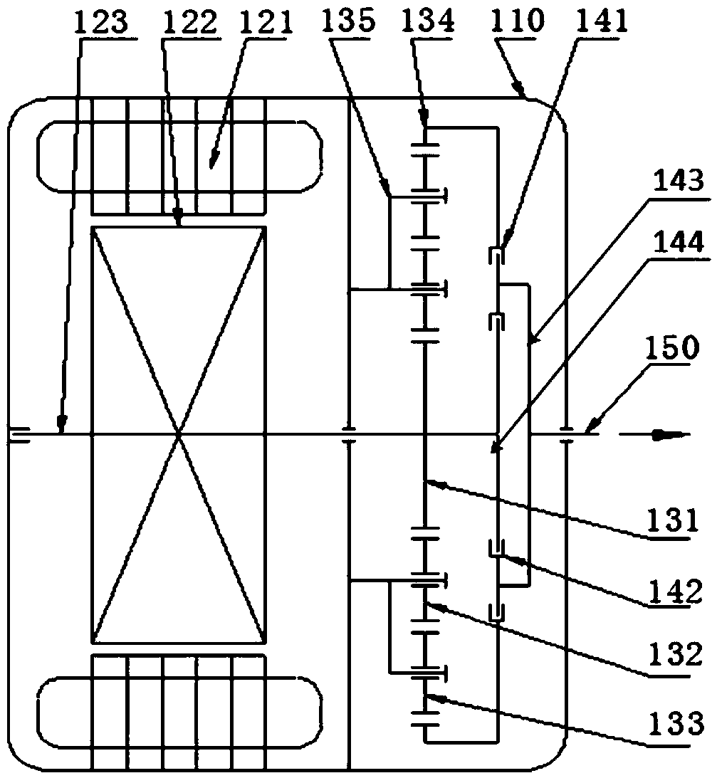
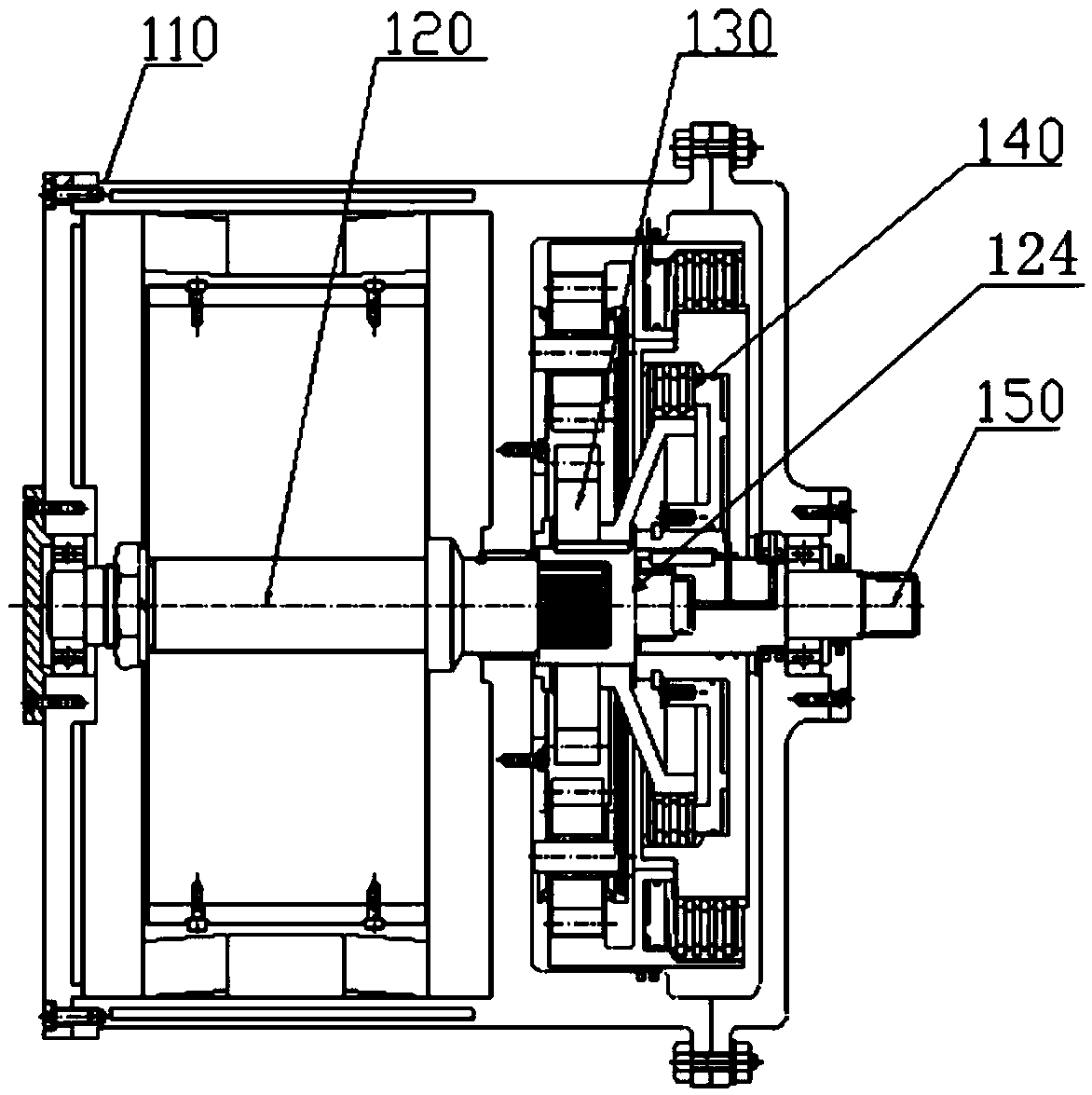
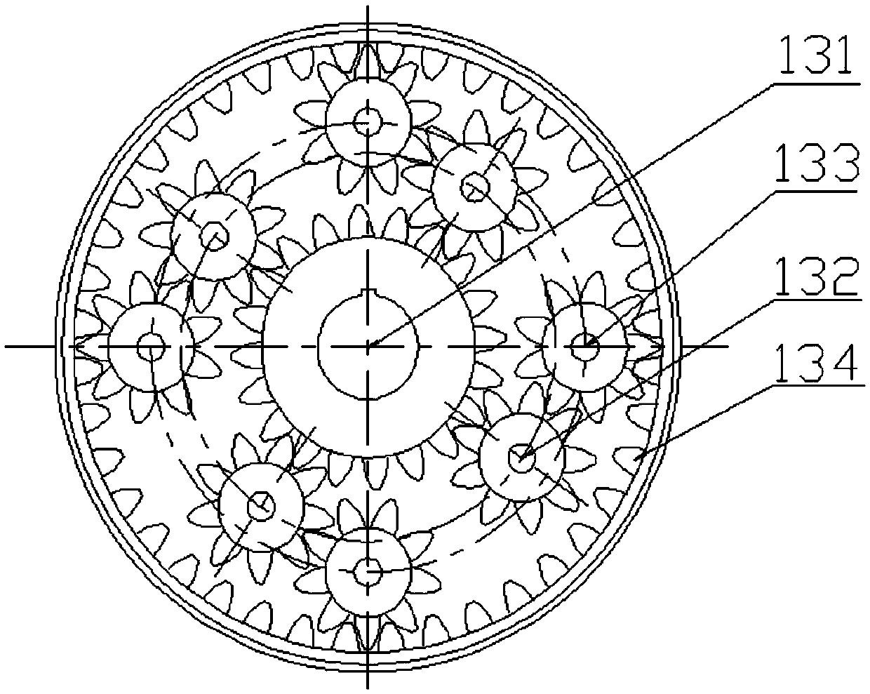
[0036] figure 1 and figure 2 Shown is the structure of the electric drive system of the single planetary row two-speed transmission, including a housing 110 , a driving motor 120 , a double planetary wheel planetary row 130 , a clutch assembly 140 and an output shaft 150 . Wherein, the speed change mechanism is composed of double planetary wheel planetary row 130 and clutch assembly 140 .

[0037] The casing 110 includes a first accommodation chamber and a second accommodation chamber, an inner wall is arranged between the first accommodation chamber and the second accommodati...


PUM


Abstract

The invention discloses an electric driving system based on a single-planet-row two-gear transmission. The electric driving system comprises a shell, a driving motor, a double-planet-gear planet row, an output shaft, a first clutch and a second clutch, the driving motor comprises a driving motor shaft, a planet carrier of the double-planet-gear planet row is jointly connected with a first planet gear and a second planet gear and fixed on the shell, a sun gear is connected with the driving motor shaft, the output shaft is rotatably supported on the shell and used for outputting power, the first clutch selectively engages and disengages an inner gear ring and the output shaft, and the second clutch selectively engages and disengages the sun gear and the output shaft; when a first gear is selected, the first clutch engages while the second clutch disengages; when a second gear is selected, the first clutch disengages while the second clutch engages. The electric driving system has few parts and is compact in structure and convenient to mount; the driving motor has two working modes as a motor and a power generator, so that vehicle energy utilization rate is increased and effect of saving energy resources is realized.

Description

technical field [0001] The invention relates to the drive field, in particular to an electric drive system based on a single-planetary two-speed transmission. Background technique [0002] Electric vehicles are new, energy-saving and environmentally friendly vehicles, especially in today's environment with severe air pollution, they have great development potential and broad application prospects. An electric vehicle uses an electric motor to replace the engine of a traditional car. The electric motor can be started with load and can meet the requirements of the car through reasonable configuration, which is a big difference from the engine. It is no longer suitable to use multi-speed transmissions on electric vehicles, but if the variable speed transmission device is cancelled, it will be difficult to meet the requirements of vehicle climbing and high-speed driving, especially for small and medium-sized vehicles, it is necessary to redesign the power of electric vehicles ac...

Claims


Application Information

Patent Timeline
IPC IPC(8): B60K17/08B60K17/02
CPCB60K17/02B60K17/08
Inventor 雷雨龙陈魏扈建龙侯利国魏庆凯于洋
Owner JILIN UNIV
Learn More