Scroll compressor and control method thereof

A scroll compressor and compression chamber technology, applied in the field of compressors, can solve the problems of increased power consumption, long suction channel, leakage, etc., and achieve the effects of increasing power consumption, avoiding air leakage, and facilitating manufacturing

Active Publication Date: 2016-04-20
ZHUHAI GREE REFRIGERATION TECH CENT OF ENERGY SAVING & ENVIRONMENTAL PROTECTION
View PDF10 Cites 3 Cited by
  • Summary
  • Abstract
  • Description
  • Claims
  • Application Information

AI Technical Summary

Problems solved by technology

[0004] The traditional scroll compressor adopts a symmetrical structure profile. Since the two pairs of suction and compression chambers are completely symmetrical and the pressures are equal, when the structure is equipped with an enthalpy increase, the two chambers can be replenished at the same time, but the symmetrical structure has shortcomings. The suction chamber inhales, compresses and exhausts at the same time. This method has the problems of long suction channel in the suction chamber and large suction resistance, which affects the suction volume and large exhaust loss at the same time.
The above problems can be avoided by changing to an asymmetric profile line. The two chambers are alternately inhaled and exhausted, with high volumetric efficiency and low loss of flow resistance. etc., the high-pressure chamber will leak to the low-pressure chamber, increasing power consumption

Method used


Image

  • Scroll compressor and control method thereof
  • Scroll compressor and control method thereof
  • Scroll compressor and control method thereof

Examples


Embodiment 1

[0034] Embodiment 1 is the first embodiment of the scroll compressor of the present invention.

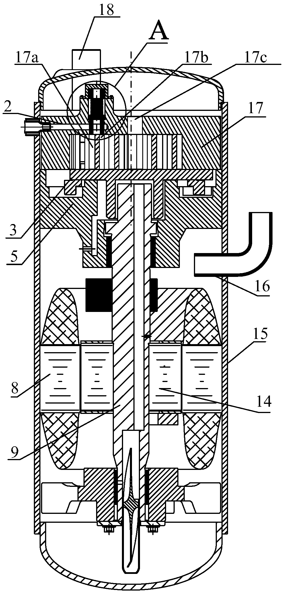
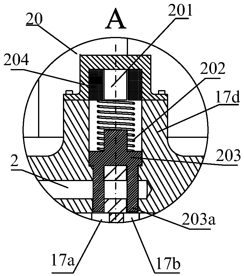
[0035] Such as Figure 1a As shown, the scroll compressor includes a casing 15, and the casing 15 is provided with a driving motor, a crankshaft 9, a movable scroll 3, and a fixed scroll 17; The scroll 3 is connected to drive the movable scroll 3 to rotate. The movable scroll 3 is provided with a movable scroll body, and the fixed scroll 17 is provided with a stationary scroll body (not shown in the figure), and energy is formed between the movable scroll body and the stationary scroll body. The first compression chamber 17a and the second compression chamber 17b that are alternately intake and exhaust; the housing 15 is provided with a suction pipe 18 and an exhaust pipe 16, which are used to supply gas to the two compression chambers and compress the The gas of the scroll compressor is discharged from the compressor, and the scroll compressor also has an enthalpy-increasing inta...

Embodiment 2

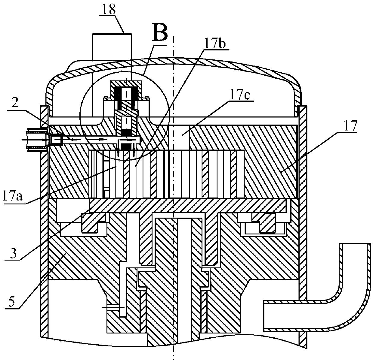
[0041] Embodiment 2 is another embodiment of the scroll compressor of the present application. Compared with Embodiment 1, the difference lies in the structure of the control device. Such as Figure 3a , 3b , 4a, and 4b, in this embodiment, the control device includes a control valve 30 and a three-way valve 26, wherein the control valve includes a cylinder and a piston 303; at least part of the cylinder is formed on the fixed base 17d of the fixed scroll 17 Above, the piston 303 is slidably arranged in the cylinder, an air chamber 305 is formed between the piston 303 and the cylinder, and the piston 303 is used to simultaneously open the first connecting channel 17e and the the second connecting passage 17f, or close at least one of the first connecting passage 17e and the second connecting passage 17f; the first end 26a of the three-way valve 26 is connected to the exhaust pipe 16, and the second The end 26b is connected to the suction pipe 18 , and the third end 26c is co...

Embodiment 3

[0046] Embodiment 3 relates to a control method for a scroll compressor, the scroll compressor includes a first compression chamber and a second compression chamber capable of alternating intake and exhaust, and an enthalpy-increasing intake passage; The method includes: communicating the first compression chamber and the second compression chamber with the enthalpy-increasing intake passage when increasing enthalpy, and disconnecting the first compression chamber from the second compression chamber when turning off enthalpy increasing The connection between the two compression chambers. Through such control, the two compression chambers can be supplemented with enthalpy increase when the enthalpy is increased, and the problem of cross-gas generation between the two compression chambers due to the pressure difference can also be avoided when the enthalpy increase is turned off.

[0047] Preferably, when the enthalpy increase is turned off, at least one of the first compression...


PUM


Abstract

The invention aims to provide a scroll compressor and a control method thereof. The scroll compressor and the control method thereof mainly aim to solve the problem that two compression cavities of an asymmetric scroll compressor are different in pressure and air leakage occurs easily in the enthalpy addition process. The scroll compressor comprises a first compression cavity, a second compression cavity and an enthalpy-adding air inlet channel, wherein the first compression cavity and the second compression cavity can alternate in air suction and air exhaust; the enthalpy-adding air inlet channel is connected to the first compression cavity and the second compression cavity through a control device, and the control device is used for enabling the first compression cavity and the second compression cavity to be communicated with the enthalpy-adding air inlet channel in the enthalpy addition process and enabling the first compression cavity and the second compression cavity to be disconnected when enthalpy addition stops. The first compression cavity and the second compression cavity are disconnected when enthalpy addition stops, and therefore the air leakage problem occurring when enthalpy addition stops can be effectively solved.

Description

technical field [0001] The invention relates to the field of compressors, in particular to a scroll compressor and a control method thereof. Background technique [0002] When the air-conditioning system using the traditional scroll compressor is used for heating in winter, as the ambient temperature drops, the density of the compressor’s suction refrigerant decreases, and the mass flow rate of the suction air also decreases, resulting in insufficient suction volume, which seriously affects the heating capacity. At the same time, when the pressure ratio increases, the discharge temperature will rise significantly, which will affect the reliability of the compressor. And as the ambient temperature decreases, the situation gradually deteriorates. [0003] In order to improve this problem, the enthalpy-increasing technology of vortex gas injection is introduced, that is, an enthalpy-increasing channel is opened at the static plate of the scroll compressor, and the saturated ga...

Claims


Application Information

Patent Timeline
Patent Type & Authority Applications(China)
IPC IPC(8): F04C18/02F04C28/00
CPCF04C18/0223F04C28/00F04C2270/185
Inventor 康小丽刘韵刘双来单彩侠陈肖汕律刚
Owner ZHUHAI GREE REFRIGERATION TECH CENT OF ENERGY SAVING & ENVIRONMENTAL PROTECTION
Why Eureka
Try Eureka