
Method for parallel shooting and bouncing rays based on dynamic load balancing technology

A dynamic load and bouncing ray technology, applied in resource allocation, program control design, instruments, etc., can solve problems such as low parallel efficiency, unclear subtask division methods, and inability to meet computing needs, so as to improve parallel efficiency and achieve good results. Scalability, the effect of good load balancing

Inactive Publication Date: 2016-04-20
SHANGHAI RADIO EQUIP RES INST
View PDF1 Cites 3 Cited by
  • Summary
  • Abstract
  • Description
  • Claims
  • Application Information

AI Technical Summary

Problems solved by technology

Based on the bouncing ray method of the graphics processing unit (GPU), the unstacked k-dimensional tree (k-dimensional tree) or the NVIDIA OptiX ray tracing engine suitable for the characteristics of the GPU is used to accelerate the ray tracing, and the electromagnetic calculation part is also transferred to the GPU side, realizing the TVU Rapid estimation of target RCS, but the above method only utilizes the parallel resources of a single GPU. Many practical engineering applications need to solve the electromagnetic scattering problem of ultra-electric large-scale complex targets. The computing resources of a single processor can no longer meet such a huge calculation. need
The SBR method based on the shared storage (OpenMP) model uses multiple central processing units (CPUs) to achieve parallel computing. This method divides the computing task into several subtasks, combines them according to the time-consuming subtasks, and assigns them to different CPUs respectively. , but the scheduling algorithm has the problems of unclear division of subtasks and low parallel efficiency

Method used


Image

  • Method for parallel shooting and bouncing rays based on dynamic load balancing technology
  • Method for parallel shooting and bouncing rays based on dynamic load balancing technology
  • Method for parallel shooting and bouncing rays based on dynamic load balancing technology

Examples


Embodiment

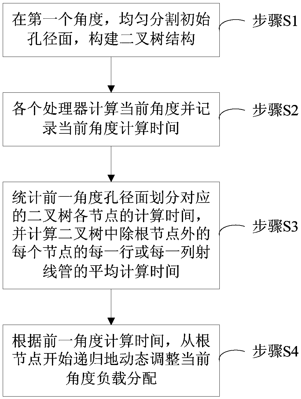
[0083] A parallel bouncing ray method based on dynamic load balancing technology, comprising the following steps:

[0084] Step S1, at the first incident angle, according to the number N of processors participating in the calculation, the initial aperture surface is evenly divided into N sub-aperture surfaces with the same area and the same number of ray tubes;

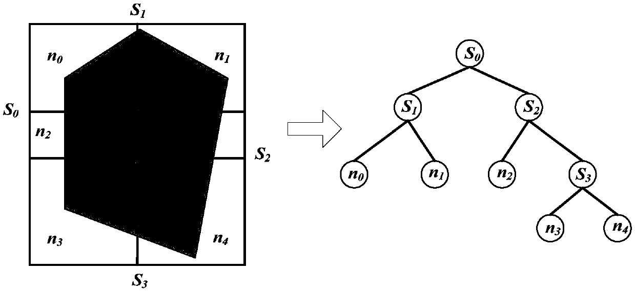
[0085] According to formula (1), the aperture surface is first divided into two sub-aperture surfaces along the longer side of the aperture surface, and one sub-aperture surface is assigned A processor calculates, another sub-aperture surface distributes The two sub-aperture surfaces will be recursively divided and allocated to processors, until the number of processors N=1 for calculating the sub-aperture surfaces, the division of the sub-aperture surfaces is terminated;

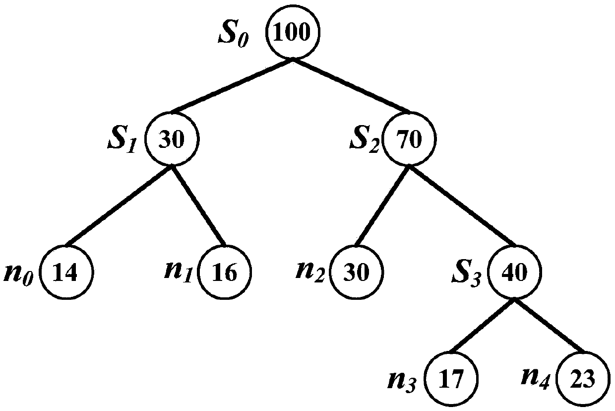
[0086] Such as figure 2 As shown, the division process of the aperture surface is shown. This process also builds a binary tree. The division...


PUM


Abstract

Provided is a method for parallel shooting and bouncing rays based on dynamic load balancing technology. The method adopts a recursion method to uniformly divide the overall initial aperture plane into sub-aperture planes covering the same area and having the same number of ray pipes. Each sub-aperture plane is provided with a processor for calculating angles. All partitioning nodes are formed to be a binary tree structure. Time is calculated according to the former angle. Starting from two sub-nodes of root nodes, load distribution at the current angle is recursively and dynamically adjusted till leaf nodes do not need to be divided. If the difference between the specific value of actual calculation time for the two sub-nodes of a node to be adjusted and ideal calculation time and that of ideal calculation time of the two sub-nodes is larger than the pre-set threshold value, loading capability needed to be adjusted is calculated and the dividing position at the current position is adjusted according to loading capability needed to be adjusted.The method for parallel shooting and bouncing rays based on dynamic load balancing technology has following beneficial effects: fine load balance between processors can be achieved such that highly-efficient parallel calculations of complicated large-sized target electromagnetic scattering can be made; and parallel efficiency of a shooting and bouncing ray method is improved.

Description

technical field [0001] The invention relates to the technical field of radar target electromagnetic simulation, in particular to a parallel bouncing ray method based on dynamic load balancing technology. Background technique [0002] The bouncing ray method (SBR) uses a combination of geometric optics and physical optics to accurately calculate the most important multiple reflections in the high-frequency scattering mechanism. Therefore, the bouncing ray method is the most successful and widely used method among high-frequency methods. It is often used to solve target radar cross-section (RCS) estimation, one-dimensional range image, two-dimensional inverse synthetic aperture radar (ISAR) imaging issues. [0003] In the bouncing ray method SBR, first define a rectangular aperture surface perpendicular to the direction of the incident wave, the aperture surface must be able to cover the projection area of ​​the target on the plane, and then divide the aperture surface into m...

Claims


Application Information

Patent Timeline
IPC IPC(8): G06F9/50G06T1/20
CPCG06F9/5027G06F2209/5012G06T1/20
Inventor 高鹏程郭良帅林云梁子长
Owner SHANGHAI RADIO EQUIP RES INST
Learn More