Battery electrolyte injection cup

A liquid injection cup and battery technology, applied in battery pack parts, circuits, electrical components, etc., can solve the problems of high corrosion risk of electrolyte, limit battery production efficiency, human and environmental damage, etc., to save manpower and material resources, The effect of reducing residual amount and reducing labor intensity

Active Publication Date: 2016-04-20
SUZHOU SECOTE PRECISION ELECTRONICS CO LTD
View PDF7 Cites 3 Cited by
  • Summary
  • Abstract
  • Description
  • Claims
  • Application Information

AI Technical Summary

Problems solved by technology

In the past, this type of operation was mostly done manually and with simple equipment. However, this method requires a long time for liquid injection, low precision of liquid injection, and a large amount of residual liquid, which greatly limits the production efficiency of the battery. In addition, the simple The liquid injection equipment is poorly sealed, which may cause electrolyte leakage or air mixing. Because the electrolyte is highly corrosive and dangerous, once it leaks, it will cause unnecessary harm to the human body and the environment. air, it may cause an explosion

Method used


Image

  • Battery electrolyte injection cup
  • Battery electrolyte injection cup

Examples


Embodiment Construction

[0023] The present invention will be further described in detail below in conjunction with the accompanying drawings and embodiments. It should be understood that the specific embodiments described herein are only used to explain the present invention, but not to limit the present invention. In addition, it should be noted that, for the convenience of description, the drawings only show some but not all structures related to the present invention, and the drawings are only for the purpose of illustration and are not drawn according to the original size.

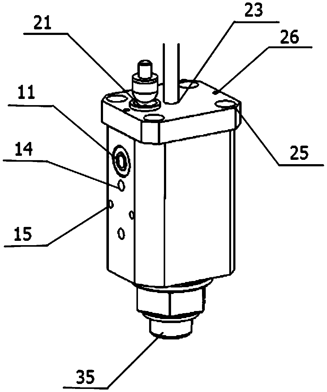
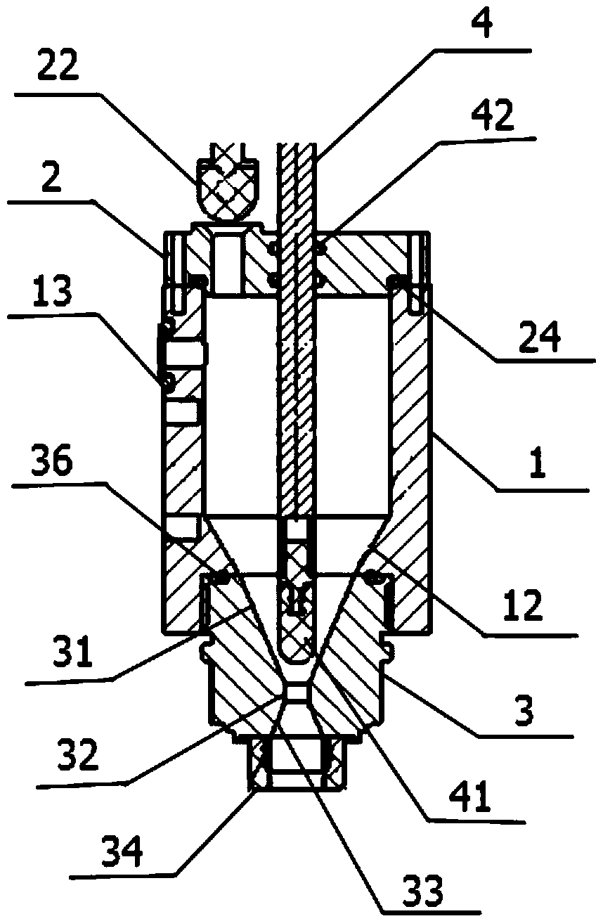
[0024] like figure 1 , figure 2 As shown, this embodiment provides a battery liquid injection cup, including a cup cover 2, a cup body 1 and a liquid injection nozzle 3, wherein the cup cover 2 is fixed on the top of the cup body 1 by bolts, and the liquid injection nozzle 3 is fastened by tightening The parts are fixed to the bottom of the lid body 1 . The cup cover 1 is provided with a liquid inlet 21 for injecting elec...


PUM


Abstract

The invention discloses a battery electrolyte injection cup. The battery electrolyte injection cup comprises a cup body, a cup cover fixed to the cup body and an electrolyte injection nozzle fixed to the bottom of the cup body. An electrolyte inlet is formed in the cup cover, and a first sealing head is arranged outside the electrolyte inlet. A vacuum opening is formed in the side face of the cup body, and a first inverted conical surface is arranged at the bottom of the inner wall of the cup body. The inner wall of the electrolyte injection nozzle is sequentially provided with a second inverted conical surface, a circular surface and a first positive conical surface from top to bottom, wherein the second inverted conical surface is tightly connected with the first inverted conical surface, the bottom of the first positive conical surface is connected with an electrolyte injection sealing nozzle, and the electrolyte injection sealing nozzle is communicated with an electrolyte outlet. A sealing opening is further formed in the cup cover, a connecting rod is inserted into the sealing opening, and a second sealing head is arranged at the end of the connecting rod and used for being matched with the circular surface. The battery electrolyte injection cup is good in sealing performance, high in electrolyte injection efficiency and precise in electrolyte injection amount, leakage of an electrolyte and electrolyte residues in the cup body are effectively avoided, time and labor are saved during work, and the automation degree of battery production is greatly increased.

Description

technical field [0001] The invention relates to the technical field of battery production equipment, in particular to a battery liquid injection cup. Background technique [0002] At present, with the wide application of lithium batteries in all walks of life, the research on lithium battery production equipment is also attracting more and more attention. In the production of lithium batteries, the electrolyte needs to be injected into the battery box through the battery injection hole. In the past, this type of operation mostly relied on manual and simple equipment to complete, but this method requires a long injection time, lower injection precision, and more residual injection, which greatly limits the production efficiency of the battery; The poor sealing performance of the liquid injection equipment may cause leakage of the electrolyte or the mixing of air. Since the electrolyte is highly corrosive and dangerous, once it leaks, it will cause unnecessary damage to the h...

Claims


Application Information

Patent Timeline
Patent Type & Authority Applications(China)
IPC IPC(8): H01M2/36H01M50/609H01M50/627H01M50/636
CPCH01M50/60Y02E60/10
Inventor 孙丰
Owner SUZHOU SECOTE PRECISION ELECTRONICS CO LTD
Why Eureka
Try Eureka