
Motor and rotor assembly thereof

An assembly and rotor technology, applied in the field of motor supporting components, can solve the problems of increased processing difficulty, complex matching structure, inconvenient production and processing, etc., and achieve the effect of reducing structural components, simplifying the overall structure, and adapting to the same specifications

Inactive Publication Date: 2016-04-20
ZHUHAI GREE REFRIGERATION TECH CENT OF ENERGY SAVING & ENVIRONMENTAL PROTECTION
View PDF3 Cites 6 Cited by
  • Summary
  • Abstract
  • Description
  • Claims
  • Application Information

AI Technical Summary

Problems solved by technology

[0003] In view of the above problems, the more common technology at present is to design the balance weight, and rivet the balance weight to the end of the rotor through rivets. Since the displacement of the compressor is different, the size and height of the eccentric portion of the rotor balance weight will also be different. If the rivet As the length varies with the height of the balance weight, there will be many kinds of rivets with different heights; if the length of the rivet needs to be used for a variety of rotors, counterbore holes will be required for the balance weight, and the matching structure between the components will also be complicated, which will lead to the overall processing of the device. Increased difficulty
At the same time, the balance weight and the rotor are riveted together. During the assembly and final assembly of the rotor assembly, a lot of special tools need to be designed to avoid the balance weight on the rotor. These tools have complex structures and low universality, which causes a lot of inconvenience to related production and processing.

Method used


Image

  • Motor and rotor assembly thereof
  • Motor and rotor assembly thereof
  • Motor and rotor assembly thereof

Examples


Embodiment Construction

[0018] The core of the present invention is to provide a rotor assembly, which has a relatively simple assembly structure, high assembly efficiency and high versatility of components; meanwhile, it provides a motor using the above rotor assembly.

[0019] In order to enable those skilled in the art to better understand the solution of the present invention, the present invention will be further described in detail below in conjunction with the accompanying drawings and specific embodiments.

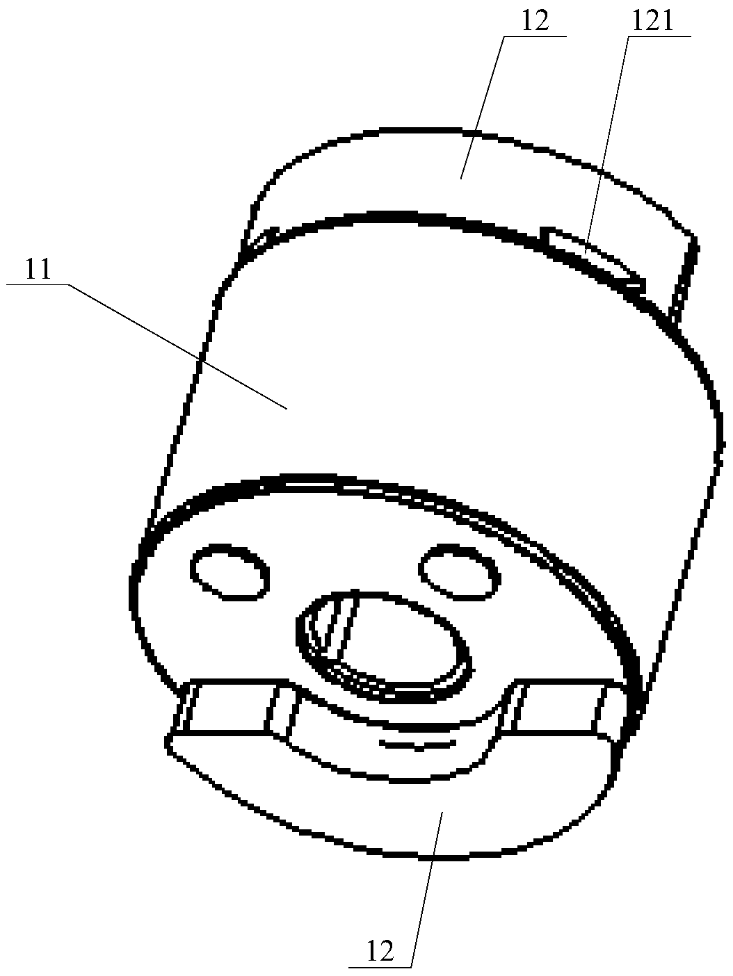
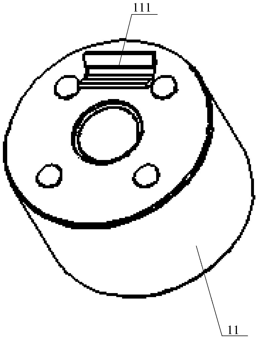
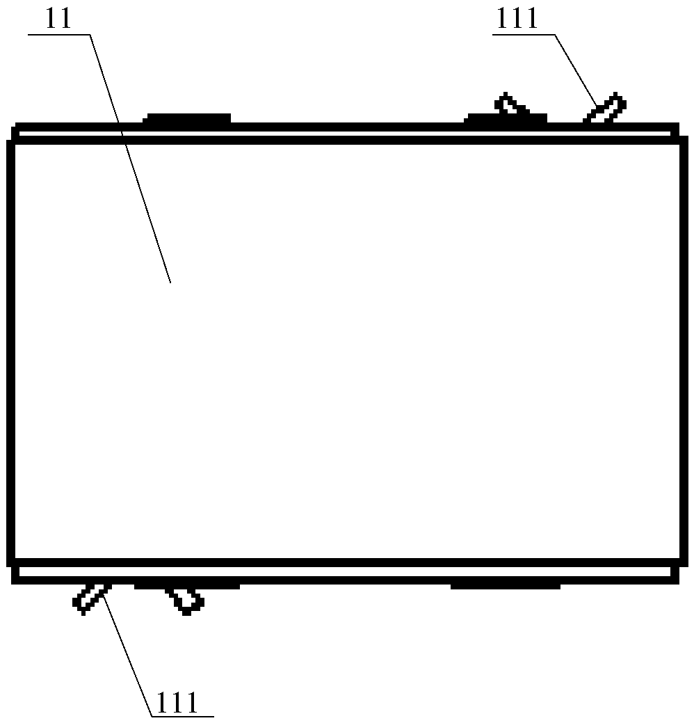
[0020] Please refer to Figure 1 to Figure 6 , figure 1 A structural schematic diagram of a rotor assembly provided for a specific embodiment of the present invention; figure 2 for figure 1 Schematic diagram of the structure of the middle rotor body; image 3 for figure 2 side view of Figure 4 for figure 1 Schematic diagram of the structure of the middle balance block; Figure 5 for Figure 4 front view of Figure 6 for Figure 5 side view.

[0021] In a specific embodiment,...


PUM


Abstract

The invention discloses a rotor assembly. The rotor assembly comprises a rotor body and a balance block which are matched with each other. The two ends of the rotor body are both provided with a clamp. The balance block is provided with clamping grooves matched with the clamps in a connected mode. In the assembling and using process, reliable assembly between the balance block and the rotor body is achieved through clamping connection between the clamps and the clamping grooves, and therefore the assembly strength of the whole assembly can be guaranteed under the condition that rivets and other auxiliary fasteners are not needed to be additionally arranged, structural components of the rotor assembly are remarkably reduced, the overall structure of the rotor assembly is simplified, and the assembly efficiency of the rotor assembly is improved; meanwhile, the clamps and the clamping grooves are matched and are consistent in specification, the assembly structure adaptability between balance blocks in different specifications and the rotor body and component universality are greatly improved, and the work condition adaption capacity of the components is improved. The invention further discloses a motor provided with the rotor assembly.

Description

technical field [0001] The invention relates to the technical field of motor matching components, in particular to a rotor assembly. The invention also relates to a motor using the rotor assembly. Background technique [0002] Due to the eccentric mass of the rotating parts of the pump body, the centrifugal force and centrifugal moment of the pump body cannot be self-balanced when the pump body is in operation. Therefore, an eccentric mass part must be added to ensure its rotational balance during actual assembly and use. [0003] In view of the above problems, the more common technology at present is to design the balance weight, and rivet the balance weight to the end of the rotor through rivets. Since the displacement of the compressor is different, the size and height of the eccentric portion of the rotor balance weight will also be different. If the rivet As the length varies with the height of the balance weight, there will be many kinds of rivets with different heigh...

Claims


Application Information

Patent Timeline
IPC IPC(8): H02K15/16
CPCH02K15/165
Inventor 张强江胜军韩东岳
Owner ZHUHAI GREE REFRIGERATION TECH CENT OF ENERGY SAVING & ENVIRONMENTAL PROTECTION
Learn More