Transmitter power calibration device and method
A power calibration and transmitter technology, applied in the field of wireless communication, can solve the problems of multi-channel radio frequency interference of the MIMO transmitter of the electronic components of the instrument, and the difficulty of maintaining the transmitting power of the transmitter, so as to ensure the accuracy of the transmitted signal power, improve the speed, The effect of strong generality and reference
- Summary
- Abstract
- Description
- Claims
- Application Information
AI Technical Summary
Problems solved by technology
Method used
Image
Examples
Embodiment 1
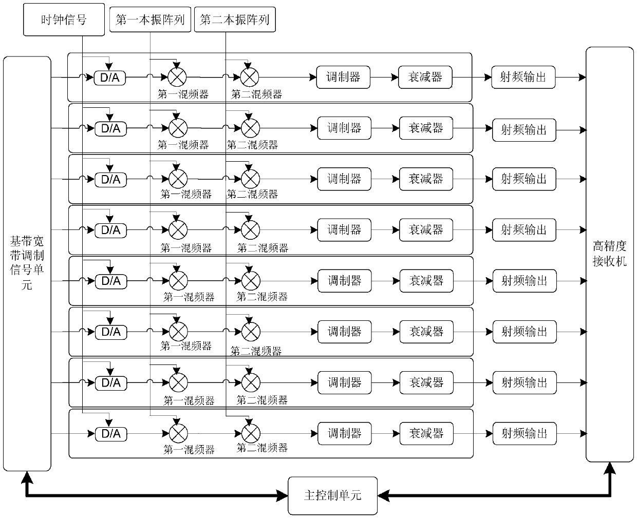
[0033] combine figure 1 A power calibration device for a transmitter includes a transmitter, a receiver and a main control unit, the transmitter is connected to the receiver, and the main control unit is connected to the transmitter and the receiver respectively.
[0034] The transmitter includes a baseband modulation signal unit and eight transmission channels. Each transmission channel is composed of a digital-to-analog converter, a first mixer, a second mixer, a modulator, an attenuator and a radio frequency output port connected in sequence. The digital-to-analog converter is connected with the baseband modulation signal unit, the radio frequency output port is connected with the receiver, and the baseband modulation signal unit is provided with a field programmable gate array.
[0035] A 614.4MHz clock signal is input to the digital-to-analog converter, a first local oscillator signal is input to the first mixer, and a second local oscillator signal is input to the second...
Embodiment 2
[0037] combine Figure 1 to Figure 3 , a method for calibrating a power calibrating device of a transmitter according to the above-mentioned embodiment 1, comprising:
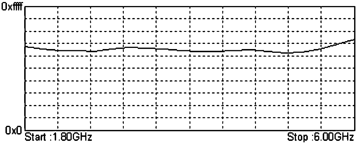
[0038] Step 1: Divide the interval. Assuming that the transmit signal bandwidth is an LTE modulated signal of 20MHz, the frequency range from 1.8GHz to 6GHz in each transmit channel is divided into N1 interval points. Since the flatness of the frequency response is not enough, the frequency response is divided into intervals The division is smaller to ensure good accuracy. The frequency response of each transmission channel is divided into N2 interval points. Both N2 and N1 are positive integers, and N2 is greater than N1.
[0039] Step 2: Attenuator calibration, perform attenuator calibration on the N1 interval points in each transmission channel, each 10dB gear of the attenuator in the range of 0dB to 120dB obtains the difference between the real attenuation value and the expected attenuation value Differenc...
PUM
 Abstract
Description
Claims
Application Information
 - R&D
- Intellectual Property
- Life Sciences
- Materials
- Tech Scout
- Unparalleled Data Quality
- Higher Quality Content
- 60% Fewer Hallucinations
Browse by: Latest US Patents, China's latest patents, Technical Efficacy Thesaurus, Application Domain, Technology Topic, Popular Technical Reports.
© 2025 PatSnap. All rights reserved.Legal|Privacy policy|Modern Slavery Act Transparency Statement|Sitemap|About US| Contact US: help@patsnap.com


