MEMS microphone manufacturing method

A manufacturing method and microphone technology, applied in the direction of electrostatic transducer microphones, sensors, electrical components, etc., can solve the problems of unfavorable CMOS process integration and large-scale production, and increase the complexity of MEMS microphone manufacturing process, so as to reduce the process complexity , improve the yield, easy to integrate the effect

Active Publication Date: 2016-04-20
SHANGHAI INTEGRATED CIRCUIT RES & DEV CENT
View PDF5 Cites 12 Cited by
  • Summary
  • Abstract
  • Description
  • Claims
  • Application Information

AI Technical Summary

Problems solved by technology

All of these have greatly increased the complexity of the existing MEMS microphone manufacturing process, which is not conducive to integration with the CMOS process and mass production

Method used


Image

  • MEMS microphone manufacturing method
  • MEMS microphone manufacturing method
  • MEMS microphone manufacturing method

Examples


Embodiment Construction

[0033] The specific embodiment of the present invention will be further described in detail below in conjunction with the accompanying drawings.

[0034] It should be noted that, in the following specific embodiments, when describing the embodiments of the present invention in detail, in order to clearly show the structure of the present invention for the convenience of description, the structures in the drawings are not drawn according to the general scale, and are drawn Partial magnification, deformation and simplification are included, therefore, it should be avoided to be interpreted as a limitation of the present invention.

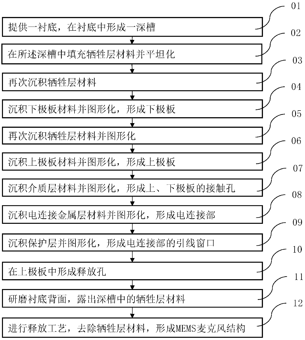
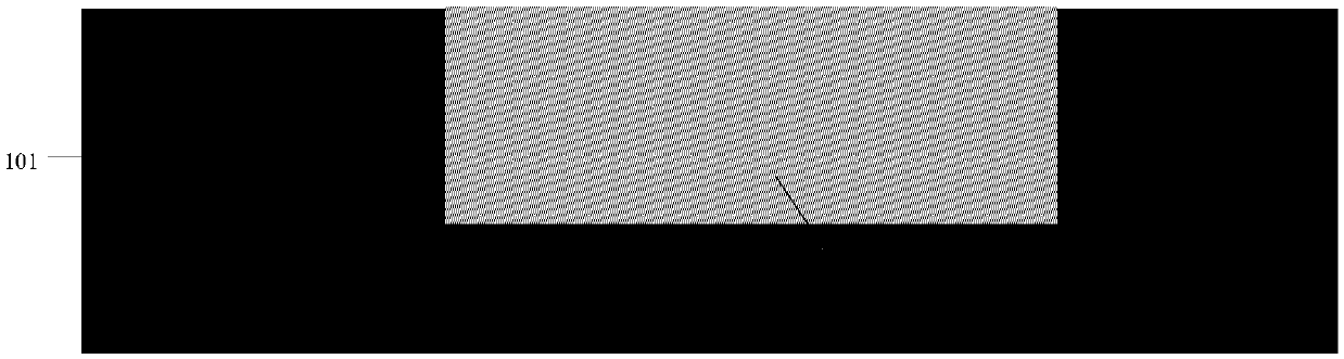
[0035] In the following specific embodiments of the present invention, please refer to figure 1 , figure 1 It is a kind of MEMS microphone manufacturing method flowchart of the present invention; Meanwhile, please refer to Figure 2-Figure 13 , Figure 2-Figure 13 is a preferred embodiment of the present invention according to figure 1 A schemati...


PUM


Abstract

The invention discloses an MEMS microphone manufacturing method. The MEMS microphone manufacturing method comprises the following steps: forming a deep groove in a substrate, filling the deep groove with a sacrificial layer material and flattening the sacrificial layer material, forming a lower electrode plate and an upper electrode plate, forming contact holes of the upper and lower electrode plates, forming a lead window, forming release holes in the upper plate electrode, grinding the back surface of the substrate, exposing the sacrificial layer material in the deep groove, carrying out a release process, and removing the sacrificial layer material, so an MEMS microphone structure can be formed without carrying out a back surface process, the complexity of the process can be greatly reduced, the process is integrated with a CMOS process more easily, and the yield is improved.

Description

technical field [0001] The invention relates to the technical field of integrated circuit micro-electro-mechanical systems (MEMS), and more particularly, relates to a method for manufacturing a MEMS microphone without a backside process. Background technique [0002] Microphones are divided into dynamic microphones and condenser microphones. The traditional dynamic microphone consists of a coil, a diaphragm and a permanent magnet. It is based on the principle that the movement of the coil in the magnetic field generates an induced current; while the main structure of the condenser microphone is two capacitor plates, which are used as the upper plate. The diaphragm (Diaphragm) and the back plate (Backplate) as the lower plate, its working principle is that the sound pressure causes the deformation of the diaphragm, resulting in a change in the capacitance value, which is converted into an electrical signal output. [0003] MEMS microphones are by far one of the most successf...

Claims


Application Information

Patent Timeline
Patent Type & Authority Applications(China)
IPC IPC(8): H04R31/00H04R19/04
CPCH04R19/04H04R31/00H04R2231/00
Inventor 袁超
Owner SHANGHAI INTEGRATED CIRCUIT RES & DEV CENT
Why Eureka
Try Eureka