

Accelerating tube, method for accelerating charged particles, and medical linear accelerator
A technology of accelerating tubes and accelerating chambers, applied in the direction of linear accelerators, pharmaceutical devices, and other medical devices, can solve the problems of obtaining electron beams and complex implementation methods, and achieve the effect of strong selectivity
- Summary
- Abstract
- Description
- Claims
- Application Information
AI Technical Summary
Problems solved by technology
Method used
Image

Examples
Embodiment Construction
[0039] In order to make the above objects, features and advantages of the present invention more comprehensible, specific embodiments of the present invention will be described in detail below in conjunction with the accompanying drawings.
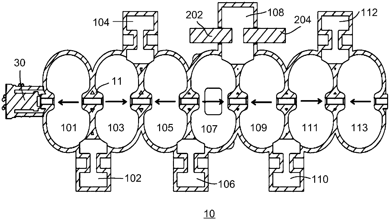
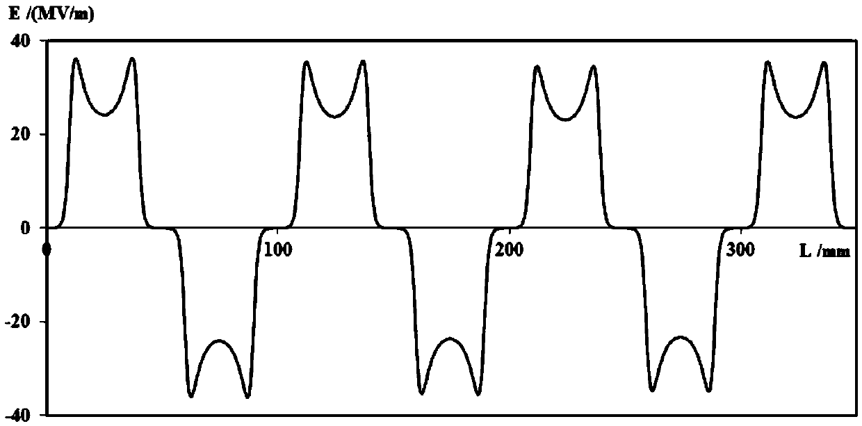
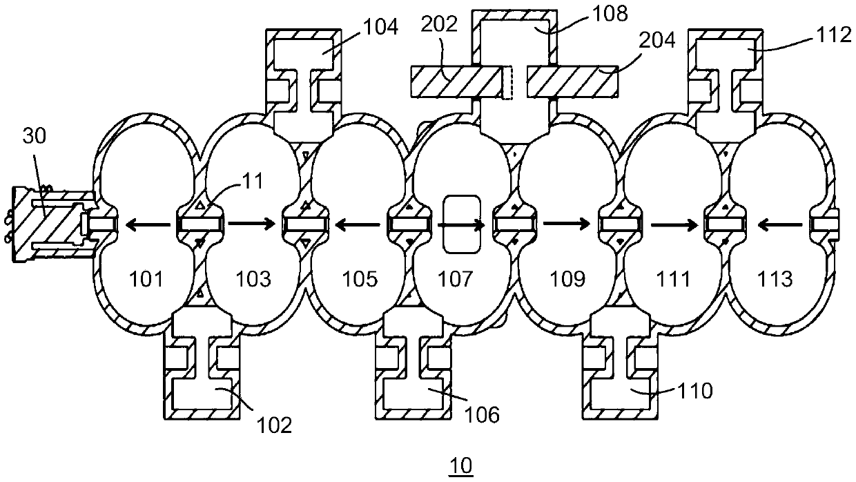
[0040] Such as figure 1 - as shown in Figure 8, figure 1 , image 3 , Figure 5 and Figure 7 The cross-sectional schematic diagrams of the accelerating tube in different modes are shown respectively, figure 2 , Figure 4 , Figure 6 and Figure 8 respectively show the figure 1 , image 3 , Figure 5 and Figure 7 Schematic diagram of the electric field distribution of each accelerating cavity corresponding to a certain moment. More specifically, in figure 2 , Figure 4 , Figure 6 And in Fig. 8, the abscissa represents the physical length of each accelerating cavity on the beam direction, and the ordinate represents the electric field intensity in each accelerating cavity, wherein, the electric field intensity is a vector, p...
PUM
 Abstract
Description
Claims
Application Information