A pulse mask device

A mask and pulse technology, which is used in current-use instruments, physiotherapy positioning, physiotherapy, etc., can solve the problems of inconvenient use, unsatisfactory use effect, unsatisfactory adhesion, etc., and achieves convenient production and structure. Reasonable, increase the effect of transdermal efficiency

Active Publication Date: 2018-07-17
嘉兴笼列电子商务有限公司
View PDF5 Cites 1 Cited by
  • Summary
  • Abstract
  • Description
  • Claims
  • Application Information

AI Technical Summary

Problems solved by technology

But in actual use, because the facial mask of this middle structural form adopts two-layer mask body and paper battery bonding to form an integral facial mask product, when consumer is using, this middle facial mask product makes it and face because of its thicker thickness. The adhesiveness of the part is not ideal, so that its use effect is not ideal; in addition, when consumers use it, in order to avoid the electronic mask product with the middle structure from slipping, it must be kept in a relatively stable posture, which will give consumers a certain degree of comfort. It brings some inconvenience to the user's life
In addition, the controller and the mask are connected by cable and can only be used in fixed beauty salons.

Method used


Image

  • A pulse mask device
  • A pulse mask device
  • A pulse mask device

Examples


Embodiment 1

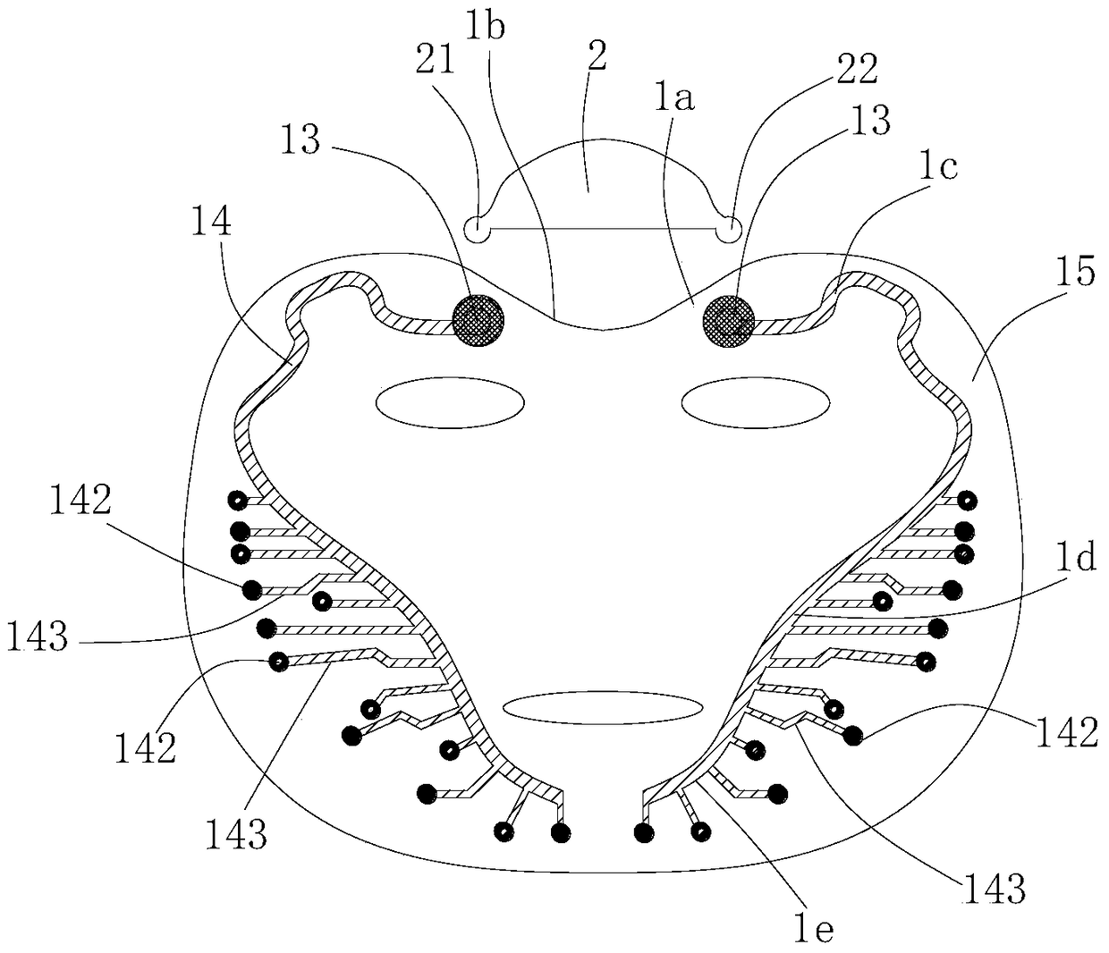
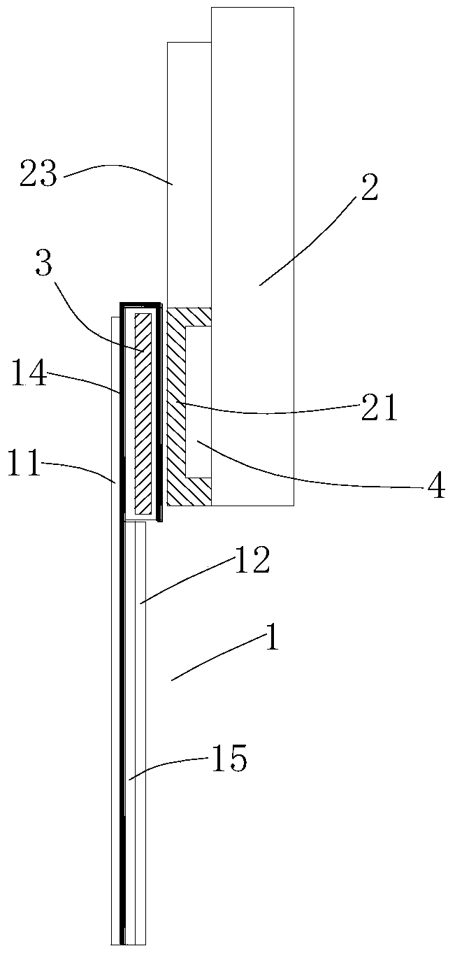
[0018] Embodiment 1: refer to Figure 1-5 . A kind of pulse facial mask device, comprises facial mask body 1 and pulse control main frame 2, described facial mask body 1 comprises inner layer 11, outer layer 12 and conductive layer, conductive layer is arranged between inner layer 11 and outer layer 12, and described conductive layer Layer comprises non-woven fabric 15 and the conductive electrode layer 14 that is distributed on both sides of non-woven fabric 15, and pulse control host computer 2 comprises positive electrode output end 21 and negative electrode output end 22, and mask body 1 comprises forehead portion 1a, and the conductive electrode layer 14 on both sides The upper end of the electrode layer 14 is respectively provided with an electrode connection part 13 near the forehead, and the pulse control host 2 is placed outside the forehead 1a of the facial mask body 1, and the positive electrode output 21 and the negative electrode output 22 of the pulse control hos...

Embodiment 2

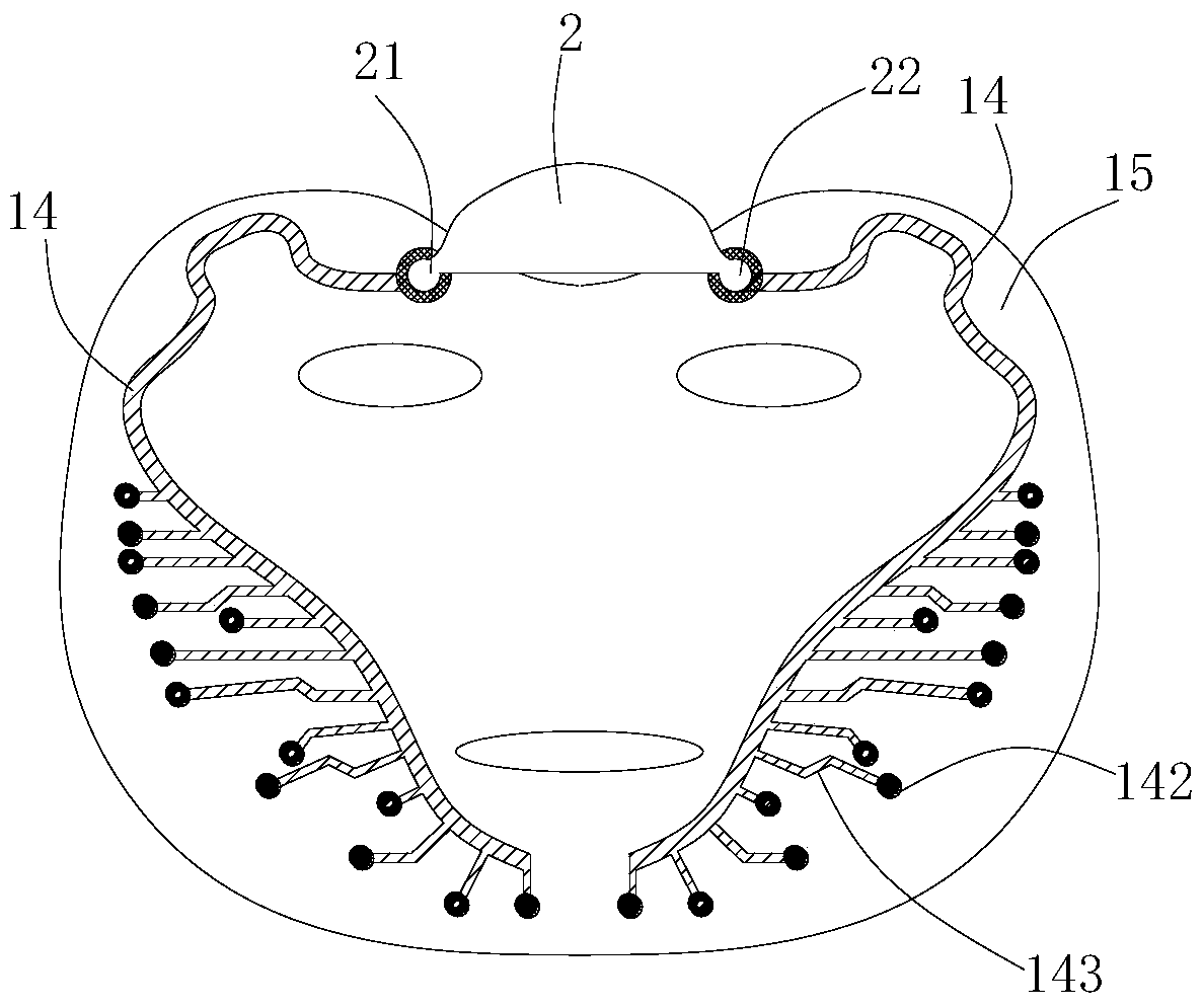
[0019] Embodiment 2: refer to Figure 1-4 . On the basis of Embodiment 1, the conductive electrode layer 14 respectively includes brow bone electrode area 1c, cheek electrode area 1d, and jaw electrode area 1e, and brow bone electrode area 1c, cheek electrode area 1d, and jaw electrode area 1e are sequentially connected in series. The conductive electrode layer 14 on one side, the electrode connecting portion 13 is disposed on the browbone electrode region 1c. A plurality of electrode nodes 142 are provided outside and inside the conductive electrode layers 14 on both sides, and each electrode node 142 is conductively connected to the conductive electrode layer 14 through a separate electrode lead 143 . A viscous glue layer 23 is pasted on the pulse control host 2 between the positive electrode output end 21 and the negative electrode output end 22 . The positive electrode output terminal 21 and the negative electrode output terminal 22 are distributed on both sides of the b...

Embodiment 3

[0020] Embodiment 3: refer to Figure 5 . On the basis of Embodiment 1, a plurality of electrode nodes 142 are provided on the inside and outside of the conductive electrode layers 14 on both sides, and each electrode node 142 is connected to the conductive electrode layer 14 through a separate electrode lead 143. connect.


PUM


Abstract

The invention relates to a pulse mask device, comprising a mask body and a pulse control host, wherein the mask body comprises an inner layer, an outer layer and a conductive layer; the conductive layer is arranged between the inner layer and the outer layer and comprises a non-woven fabric and conductive electrode layers on two sides of the non-woven fabric; the pulse control host comprises a positive electrode output end and a negative electrode output end; the mask body comprises a forehead portion, an electrode connecting portion is separately formed close to the forehead portion at the upper ends of the conductive electrode layers on the two sides, the pulse control host is arranged outside the forehead portion of the mask body, and the positive electrode output end and the negative electrode output end of the pulse control host are respectively electrically connected with the electrode connecting portions on the two sides of the forehead portion.

Description

technical field [0001] The invention relates to a mask, especially a pulse mask device. Background technique [0002] In the prior art, the publication number is: CN201658753U, the name is a conductive mask device, which includes a controller and a conductive mask, the controller includes a processing unit, a control unit connected to the processing unit and a An electrical output unit electrically connected to the unit, the electrical output unit has a first electrode and a second electrode; the conductive film includes a conductive layer electrically connected to the first electrode, an insulating layer arranged on the periphery of the conductive film One end of the conductive fixing part is electrically connected to the second electrode, and the other end is attached to the human skin, and the human skin is used as a resistor to make it in contact with the second electrode. The conductive layer is electrically connected, and the fixing of human skin and the conductive ma...

Claims


Application Information

Patent Timeline
Patent Type & Authority Patents(China)
IPC IPC(8): A61N1/32A61H39/00
CPCA61H39/002A61H2205/022A61N1/325A61N1/327A61N1/328
Inventor 赵阳王俊赵晖
Owner 嘉兴笼列电子商务有限公司
Why Eureka
Try Eureka