Electrode structure of electrolyte thermobattery and electrolyte thermobattery preparation method

A thermoelectric battery and electrode structure technology, applied in the manufacture/processing of thermoelectric devices, thermoelectric device components, thermoelectric devices using only Peltier or Seebeck effect, etc., can solve problems such as low thermoelectric efficiency, reduce heat loss and save energy Electrode material, cost reduction effect

Active Publication Date: 2017-02-22
INST OF CHEM MATERIAL CHINA ACADEMY OF ENG PHYSICS
View PDF4 Cites 6 Cited by
  • Summary
  • Abstract
  • Description
  • Claims
  • Application Information

AI Technical Summary

Problems solved by technology

However, the thermoelectric efficiency of the current electrolyte thermoelectric battery is low

Method used


Image

  • Electrode structure of electrolyte thermobattery and electrolyte thermobattery preparation method
  • Electrode structure of electrolyte thermobattery and electrolyte thermobattery preparation method
  • Electrode structure of electrolyte thermobattery and electrolyte thermobattery preparation method

Examples


preparation example Construction

[0048] A method for preparing an electrolyte thermoelectric battery, comprising the following steps:

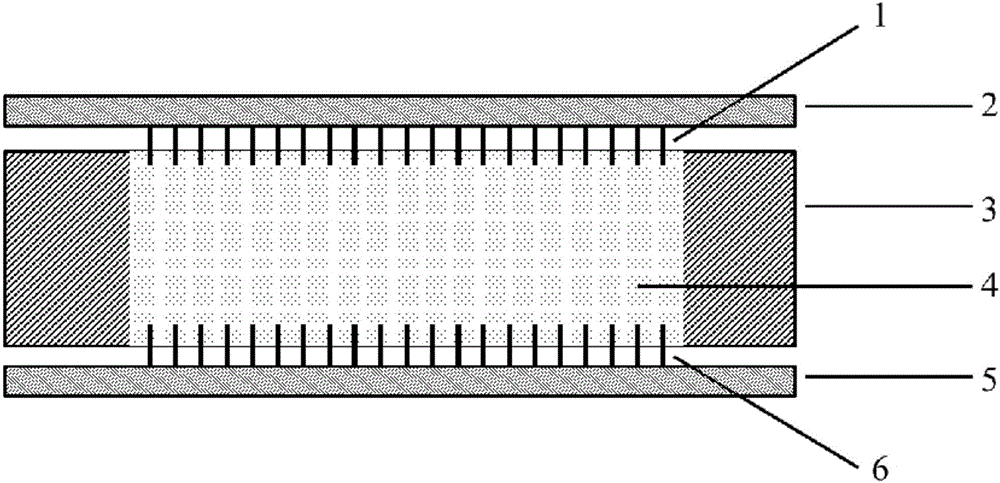
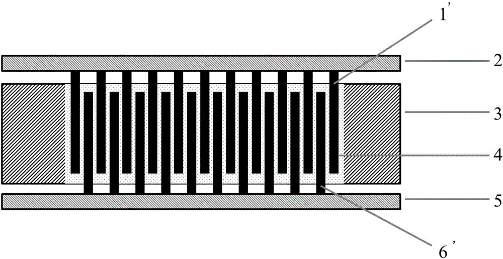
[0049] Step 1, designing the size, density and position of the column array electrode or sheet array electrode;

[0050] Use 3dmax or Autocad software to design and draw battery hot-end electrodes and battery cold-end electrodes with column arrays or sheet arrays, including determining the size of battery hot-end electrodes and battery cold-end electrodes, as well as the configuration of column array electrodes or sheet array electrodes Single quantity and position; design and draw the shape specification and size of insulating partition 3 at the same time;

[0051] Step 2: Use 3D printing technology to print out the battery hot terminal electrode, the battery cold terminal electrode and the insulating separator 3 respectively;

[0052] Use 3D printing technology to directly print the model diagram drawn above, wherein the raw materials used for the battery hot end electrode...

Embodiment 1

[0056] Example 1: Autocad software is used to design and draw electrodes with a column array, wherein the diameter of a single column array electrode is 0.5 mm, the length is 2 mm, and the distance between two adjacent column array electrodes is 1 mm. 3D printing technology is used to print the hot end, cold end electrodes, and insulating partitions respectively; the raw materials used for the hot end and cold end electrodes are titanium alloy powder; the material of the insulating partitions is ABS resin. After the hot-end and cold-end electrodes are printed, a 100-nm platinum layer is further vapor-deposited on the surface of the pillar array as an electrocatalytic active material. Put the hot-end electrode on the bottom, and then place the insulating partition on it to ensure that the column array part of the hot-end electrode completely enters the electrolyte groove part of the insulating partition; after sealing the hot-end electrode and the insulating partition, The elec...

Embodiment 2

[0057] Embodiment 2: adopt Autocad software to design and draw the electrode with slice array, wherein the length, width and height of each slice array electrode are 4 centimeters, 1 millimeter, and 2 centimeters respectively, and the distance between two adjacent array electrodes is 1 mm. 3D printing technology is used to print out the hot-end, cold-end electrodes, and insulating partitions respectively; the raw materials used for the hot-end and cold-end electrodes are stainless steel powder; the material of the insulating partitions is polycarbonate resin. After the hot-end and cold-end electrodes are printed, a 50-nm platinum layer is further vapor-deposited on the surface of the chip array as an electrocatalytic active material. Put the hot-end electrode on the bottom, and then place the insulating partition on it to ensure that the plate array part of the hot-end electrode completely enters the electrolyte groove part of the insulating partition; after sealing the hot-en...


PUM


Abstract

The invention discloses an electrode structure of an electrolyte thermobattery. The electrode structure comprises a battery hot-end electrode and a battery cold-end electrode which are positioned on two sides of an insulating partition with an electrolyte groove respectively, the electrolyte groove of the insulating partition is filled with a redox couple electrolyte, and the battery hot-end electrode comprises a battery hot-end current collector and array electrodes arranged on the battery hot-end current collector; the battery cold-end electrode comprises a battery cold-end current collector and array electrodes arranged on the battery cold-end current collector, and the array electrodes are divided column array electrodes and sheet array electrodes. Effective using area of the electrode structure is increased, and thermal transition efficiency of the electrolyte thermobattery is improved substantially.

Description

technical field [0001] The invention relates to the technical field of manufacturing an electrolyte thermoelectric battery, in particular to an electrolyte thermoelectric battery with a high-efficiency electrode structure and a preparation method for the electrolyte thermoelectric battery. Background technique [0002] The energy crisis has always been a major problem faced by countries all over the world. Due to the limited nature of non-renewable energy, people's demand for renewable energy and clean energy is unprecedentedly high. Using thermoelectric batteries to convert waste heat energy into electrical energy is one of the effective ways to solve the energy crisis. The electrolyte thermoelectric battery is different from the solid semiconductor thermoelectric battery. The electrolyte thermoelectric battery is a thermoelectric battery based on redox electrolyte pairs. Its working principle is to use redox electrolyte pairs to undergo different redox reactions under diff...

Claims


Application Information

Patent Timeline
Patent Type & Authority Applications(China)
IPC IPC(8): H01L35/32H01L35/02H01L35/34
CPCH10N10/80H10N10/01H10N10/17
Inventor 张龙王军杨云涛刘有松李瑞
Owner INST OF CHEM MATERIAL CHINA ACADEMY OF ENG PHYSICS
Why Eureka
Try Eureka