Stirring head for friction stir welding

A friction stir welding and stirring head technology, used in welding equipment, non-electric welding equipment, metal processing equipment, etc., can solve the problems of easily damaged connecting parts, uncompact structure, difficult control, etc., to reduce the spindle unit structure, improve The effect of welding stability and simple spindle structure

Inactive Publication Date: 2016-04-27
河南正航主轴科技有限公司
View PDF10 Cites 10 Cited by
  • Summary
  • Abstract
  • Description
  • Claims
  • Application Information

AI Technical Summary

Problems solved by technology

Therefore, under the requirements of this kind of stirring head welding process, if the welded line is designed to have a corner or a change of direction, it is necessary to form a corner or change of direction weld. At the corner or change of direction, due to the necessity of the technology of the inclination angle of the stirring head, The azimuth of the inclination angle of the stirring head needs to be changed when turning, which requires the control system to control the connecting parts of the main shaft unit to make corresponding inclination changes. Due to the high degree of automation of the friction stir welding equipment, this kind of

Method used


Image

  • Stirring head for friction stir welding
  • Stirring head for friction stir welding
  • Stirring head for friction stir welding

Examples


Example Embodiment

[0011] In order to more fully explain the implementation of the present invention, an implementation example of the present invention is provided. These implementation examples are merely illustrative of the present invention, and do not limit the scope of the present invention.
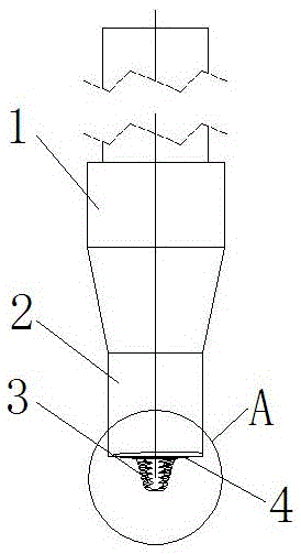
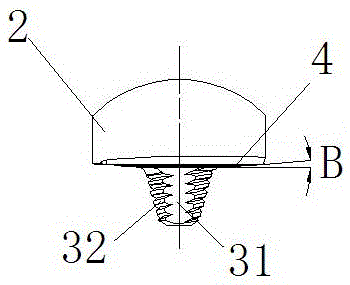
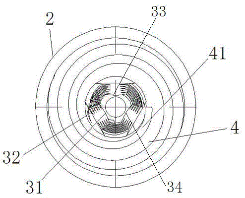
[0012] The present invention will be explained in further detail with reference to the drawings. In the drawings, the marks are as follows: 1: mixing head clamping part; 2: mixing head shoulder; 3: stirring needle; 31: inclined surface a on the stirring needle; 33: stirring needle Upper inclined surface b; 34: inclined surface c on the stirring needle; 32: spiral groove on the stirring needle; 4: bottom surface of the stirring head shoulder; 41: involute spiral groove; as shown in the figure, a friction stir The welding stirring head includes the stirring head clamping part 1 and the stirring head shoulder 2. The stirring needle 3 is located under the stirring head shoulder 2. The bottom surface 4 of th...


PUM


Abstract

The invention discloses a stirring head for friction stir welding, and belongs to the field of friction stir welding technical devices. The stirring head comprises a stirring head shaft shoulder; a stirring needle is positioned below the stirring head shaft shoulder; the bottom surface of the stirring head shaft shoulder is an inclined surface, and is a contact surface between the shaft shoulder and a welded workpiece; the direction of the inclined surface is as follows: when the stirring needle is downwards, the inclined surface is inclined from the center of the bottom surface to the outer and upper directions; and an included angle between the inclined surface and a vertical line of axis of the stirring head is 1-10 degrees. The stirring heads forms a compact welding line, improves the quality of the welding line, and guarantees high reliability and stability of the welding line.

Description

technical field [0001] The invention relates to a friction stir welding component, in particular to a friction stir welding stirring head, which belongs to the field of friction stir welding technical devices. Background technique [0002] Friction stir welding is mainly aimed at the connection of non-ferrous metals such as aluminum alloys. Its advantages lie in the high quality of the weld seam formed, small deformation, no pollution, no smoke and spatter during the welding process, low noise, energy saving and environmental protection, etc.; therefore, stirring The field of application of friction welding technology is constantly expanding. Stirring head is the direct core component involved in friction stir welding. Its structural design determines the quality of friction stir welding seam, welding process, welding spindle unit structure and its service life. When the existing stirring head performs friction stir welding, there needs to be a certain angle between the axi...

Claims


Application Information

Patent Timeline
IPC IPC(8): B23K20/12B23K20/26
CPCB23K20/122B23K20/1245
Inventor 光晓欢周正勇
Owner 河南正航主轴科技有限公司
Why Eureka
Try Eureka