Superfinishing machine

A technology of superfinishing machine and transmission mechanism, applied in the field of superfinishing machine, can solve the problems of redundant equipment, low efficiency, high cost, etc., and achieve the effect of strong adaptability, high reliability, high precision and high quality superfinishing

Active Publication Date: 2016-04-27
浙江陀曼智能科技股份有限公司
View PDF15 Cites 6 Cited by
  • Summary
  • Abstract
  • Description
  • Claims
  • Application Information

AI Technical Summary

Problems solved by technology

[0006] The technology disclosed in this document solves the problem of adaptability to different processing objects proposed above to a certain extent, but adopts the technical solution that the electric spindle and the swing head lifting mechanism are two sets, which are respectively installed above the working translation mechanism. , complex equipment, low efficiency, high cost, adaptability to different processing objects and coordination of functions of various components to achieve high-precision and high-quality ultra-finishing, the above-mentioned literature disclosures and prior art cannot solve it well
[0007] In the existing superfinishing machine technology, due to the different characteristics of the processed bearing inner ring and bearing outer ring, the superfinishing machine used to process the bearing inner ring and the superfinishing machine used to process the bearing outer ring need to be separated. Design and purchase, or use one piece of equipment, but there are a large number of different device structures for different workpieces on the equipment, which need to be replaced from time to time, resulting in high cost and low efficiency

Method used


Image

  • Superfinishing machine
  • Superfinishing machine
  • Superfinishing machine

Examples


Embodiment Construction

[0026] Various preferred embodiments of the present invention will be described below with reference to the accompanying drawings. The following description with reference to the accompanying drawings is provided to assist understanding of example embodiments of the invention as defined by the claims and their equivalents. It includes various specific details to aid in understanding but they are to be regarded as exemplary only. Accordingly, those of ordinary skill in the art will recognize that various changes and modifications of the embodiments described herein can be made without departing from the scope and spirit of the invention. Also, detailed descriptions of functions and constructions well-known in the art will be omitted to make the description clearer and more concise.

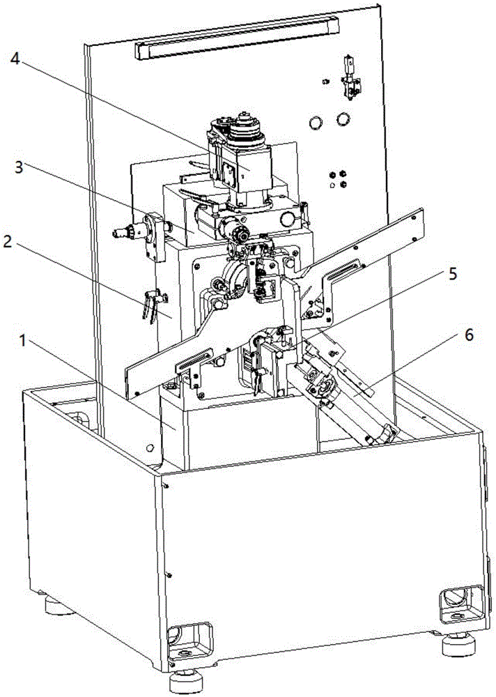
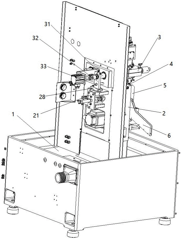
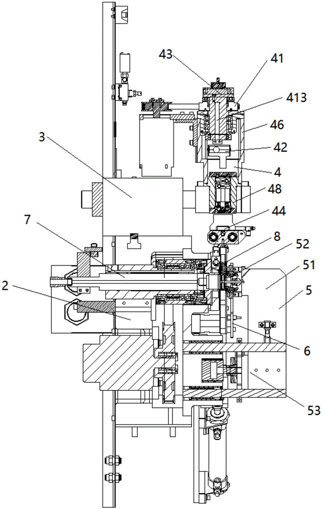
[0027] Such as Figure 1 to Figure 4As shown, a superfinishing machine includes a bed part 1, a headstock part 2, a superfinishing transmission mechanism 3, a superfinishing mechanism 4, a pressi...


PUM


Abstract

A superfinishing machine comprises a machine tool bed component, a spindle box component, a superfinishing transmission mechanism, a superfinishing mechanism, a pressing mechanism, a feed mechanism, a universal spindle component and an adjustable spindle component, wherein the superfinishing mechanism is mounted on the superfinishing transmission mechanism and is driven by the superfinishing transmission mechanism; the adjustable spindle component is mounted at an end part of the universal spindle component; the adjustable spindle component and the superfinishing mechanism are located on the same side of the spindle box component; the pressing mechanism and the feed mechanism are mounted at the lower part of the spindle box component and are located on the same side as the adjustable spindle component; the pressing mechanism, the feed mechanism and the adjustable spindle component together form a space for accommodating a to-be-processed workpiece; and the superfinishing mechanism is located above the space. The superfinishing machine can be adapted to different machining environments, can be applied to superfinishing the inner ring and outer ring of a bearing at the same time, is well adapted to different objects of machining, is convenient and accurate in process action adjustment and high in reliability, and can coordinate the functions of all the components to realize high-precision and high-quality superfinishing.

Description

technical field [0001] The invention relates to a super precision machine. Background technique [0002] Superfinishing is the finishing process of the finished surface with fine-grained oilstone mounted on the vibrating head. Superfinishing is generally arranged after the fine grinding process, and its machining allowance is only a few microns, which is suitable for machining the outer circle, inner circle, plane, groove surface and spherical surface of crankshafts, rolls, bearing rings and various precision parts. The superfinishing machine is a kind of precision equipment for this kind of processing. The oilstone is pressed against the rotating workpiece with a lower pressure to form a surface contact state. At the same time, the oilstone vibrates at a higher frequency in the axial direction to finely polish the workpiece. surface. The superfinishing machine can greatly improve the roughness in a short period of time. Because it is processed under low pressure, the surf...

Claims


Application Information

Patent Timeline
Patent Type & Authority Applications(China)
IPC IPC(8): B24B35/00B24B47/16B24B41/00B24B41/06
CPCB24B35/00B24B41/005B24B41/06B24B47/16
Inventor 王军张旭光
Owner 浙江陀曼智能科技股份有限公司
Why Eureka
Try Eureka